
Datasheet


Electrical characteristics STM32L151x6/8/B, STM32L152x6/8/B
102/131 DocID17659 Rev 9
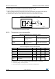
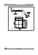
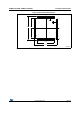
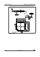
Figure 31. 12-bit buffered /non-buffered DAC
1. The DAC integrates an output buffer that can be used to reduce the output impedance and to drive external
loads directly without the use of an external operational amplifier. The buffer can be bypassed by
configuring the BOFFx bit in the DAC_CR register.
6.3.19 Temperature sensor characteristics
5. Difference between the value measured at Code (0x800) and the ideal value = V
REF+
/2.
6. Difference between the value measured at Code (0x001) and the ideal value.
7.
Difference between ideal slope of the transfer function and measured slope computed from code 0x000 and
0xFFF when buffer is OFF, and from code giving 0.2 V and (V
DDA
– 0.2) V when buffer is ON.
8. In buffered mode, the output can overshoot above the final value for low input code (starting from min value).
R
LOAD
C
LOAD
Buffered/Non-buffered DAC
DAC_OUTx
Buffer(1)
12-bit
digital to
analog
converter
ai17157V2
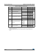
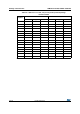
Table 58. Temperature sensor calibration values
Calibration value name Description Memory address
TS_CAL1
TS ADC raw data acquired at
temperature of 30 °C,
V
DDA
= 3 V
0x1FF8 007A-0x1FF8 007B
TS_CAL2
TS ADC raw data acquired at
temperature of 110 °C
V
DDA
= 3 V
0x1FF8 007E-0x1FF8 007F
Table 59. Temperature sensor characteristics
Symbol Parameter Min Typ Max Unit
T
L
(1)
1. Guaranteed by characterization, not tested in production.
V
SENSE
linearity with temperature - ±1 ±2°C
Avg_Slope
(1)
Average slope 1.48 1.61 1.75 mV/°C
V
110
Voltage at 110°C ±5°C
(2)
2. Measured at V
DD
= 3 V ±10 mV. V110 ADC conversion result is stored in the TS_CAL2 byte.
612 626.8 641.5 mV
I
DDA(TEMP)
(3)
Current consumption - 3.4 6 µA
t
START
(3)
3. Guaranteed by design, not tested in production.
Startup time - - 10
µs
T
S_temp
(4)(3)
4. Shortest sampling time can be determined in the application by multiple iterations.
ADC sampling time when reading the
temperature
10 - -