STM32L15xx6/8/B Ultra-low-power 32-bit MCU ARM-based Cortex-M3, 128KB Flash, 16KB SRAM, 4KB EEPROM, LCD, USB, ADC, DAC Datasheet - production data Features • Ultra-low-power platform – 1.65 V to 3.6 V power supply – -40°C to 85°C/105°C temperature range – 0.3 µA Standby mode (3 wakeup pins) – 0.9 µA Standby mode + RTC – 0.57 µA Stop mode (16 wakeup lines) – 1.
Contents STM32L151x6/8/B, STM32L152x6/8/B Contents 1 Introduction . . . . . . . . . . . . . . . . . . . . . . . . . . . . . . . . . . . . . . . . . . . . . . . . 8 2 Description . . . . . . . . . . . . . . . . . . . . . . . . . . . . . . . . . . . . . . . . . . . . . . . . . 9 3 2/131 2.1 Device overview . . . . . . . . . . . . . . . . . . . . . . . . . . . . . . . . . . . . . . . . . . . . 10 2.2 Ultralow power device continuum . . . . . . . . . . . . . . . . . . . . . . . . . . . . . . . .11 2.
STM32L151x6/8/B, STM32L152x6/8/B 3.16 Contents 3.15.1 General-purpose timers (TIM2, TIM3, TIM4, TIM9, TIM10 and TIM11) . 27 3.15.2 Basic timers (TIM6 and TIM7) . . . . . . . . . . . . . . . . . . . . . . . . . . . . . . . . 27 3.15.3 SysTick timer . . . . . . . . . . . . . . . . . . . . . . . . . . . . . . . . . . . . . . . . . . . . . 27 3.15.4 Independent watchdog (IWDG) . . . . . . . . . . . . . . . . . . . . . . . . . . . . . . . 27 3.15.5 Window watchdog (WWDG) . . . . . . . . . . . . . . .
Contents 7 STM32L151x6/8/B, STM32L152x6/8/B 6.3.9 Memory characteristics . . . . . . . . . . . . . . . . . . . . . . . . . . . . . . . . . . . . . 77 6.3.10 EMC characteristics . . . . . . . . . . . . . . . . . . . . . . . . . . . . . . . . . . . . . . . . 78 6.3.11 Electrical sensitivity characteristics . . . . . . . . . . . . . . . . . . . . . . . . . . . . 80 6.3.12 I/O current injection characteristics . . . . . . . . . . . . . . . . . . . . . . . . . . . . 80 6.3.
STM32L151x6/8/B, STM32L152x6/8/B List of tables List of tables Table 1. Table 2. Table 3. Table 4. Table 5. Table 6. Table 7. Table 8. Table 9. Table 10. Table 11. Table 12. Table 13. Table 14. Table 15. Table 16. Table 17. Table 18. Table 19. Table 20. Table 21. Table 22. Table 23. Table 24. Table 25. Table 26. Table 27. Table 28. Table 29. Table 30. Table 31. Table 32. Table 33. Table 34. Table 35. Table 36. Table 37. Table 38. Table 39. Table 40. Table 41. Table 42. Table 43. Table 44. Table 45.
List of tables Table 49. Table 50. Table 51. Table 52. Table 53. Table 54. Table 55. Table 56. Table 57. Table 58. Table 59. Table 60. Table 61. Table 62. Table 63. Table 64. Table 65. Table 66. Table 67. Table 68. Table 69. Table 70. Table 71. 6/131 STM32L151x6/8/B, STM32L152x6/8/B SPI characteristics . . . . . . . . . . . . . . . . . . . . . . . . . . . . . . . . . . . . . . . . . . . . . . . . . . . . . . . 90 USB startup time. . . . . . . . . . . . . . . . . . . . . . . . . . . . . . . . . . . . . .
STM32L151x6/8/B, STM32L152x6/8/B List of figures List of figures Figure 1. Figure 2. Figure 3. Figure 4. Figure 5. Figure 6. Figure 7. Figure 8. Figure 9. Figure 10. Figure 11. Figure 12. Figure 13. Figure 14. Figure 15. Figure 16. Figure 17. Figure 18. Figure 19. Figure 20. Figure 21. Figure 22. Figure 23. Figure 24. Figure 25. Figure 26. Figure 27. Figure 28. Figure 29. Figure 30. Figure 31. Figure 32. Figure 33. Figure 34. Figure 35. Figure 36. Figure 37. Figure 38. Figure 39. Figure 40. Figure 41.
Introduction 1 STM32L151x6/8/B, STM32L152x6/8/B Introduction This datasheet provides the ordering information and mechanical device characteristics of the STM32L151xx and STM32L152xx ultralow power ARM Cortex-M3 based microcontrollers product line. The ultralow power STM32L15xxx family includes devices in 3 different package types: from 48 to 100 pins.
STM32L151x6/8/B, STM32L152x6/8/B 2 Description Description The ultralow power STM32L15xxx incorporates the connectivity power of the universal serial bus (USB) with the high-performance ARM Cortex-M3 32-bit RISC core operating at a 32 MHz frequency, a memory protection unit (MPU), high-speed embedded memories (Flash memory up to 128 Kbytes and RAM up to 16 Kbytes) and an extensive range of enhanced I/Os and peripherals connected to two APB buses.
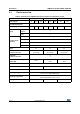
Description 2.1 STM32L151x6/8/B, STM32L152x6/8/B Device overview Table 2. Ultralow power STM32L15xxx device features and peripheral counts Peripheral Flash (Kbytes) STM32L15xCx 32 64 128 STM32L15xRx 32 Data EEPROM (Kbytes) RAM (Kbytes) Timers Communication interfaces 10 16 10 6 Basic 2 SPI 2 I2C 2 USART 3 USB 1 LCD (STM32L152xx Only) COM x SEG Operating temperatures 16 10 16 83 1 14 channels 1 20 channels 1 24 channels 2 2 4x32 8x28 4x18 4x44 8x40 2 13 20 Max.
STM32L151x6/8/B, STM32L152x6/8/B 2.2 Description Ultralow power device continuum The ultralow power STM32L151xx and STM32L152xx are fully pin-to-pin and software compatible. Besides the full compatibility within the family, the devices are part of STMicroelectronics microcontrollers ultralow power strategy which also includes STM8L101xx and STM8L15xx devices. The STM8L and STM32L families allow a continuum of performance, peripherals, system architecture and features.
Functional overview 3 STM32L151x6/8/B, STM32L152x6/8/B Functional overview Figure 1 shows the block diagrams. Figure 1.
STM32L151x6/8/B, STM32L152x6/8/B 3.1 Functional overview Low power modes The ultralow power STM32L15xxx supports dynamic voltage scaling to optimize its power consumption in run mode. The voltage from the internal low-drop regulator that supplies the logic can be adjusted according to the system’s maximum operating frequency and the external voltage supply: • In Range 1 (VDD range limited to 1.71-3.6 V), the CPU runs at up to 32 MHz (refer to Table 17 for consumption).
Functional overview STM32L151x6/8/B, STM32L152x6/8/B HSE crystal oscillators are disabled. The voltage regulator is in the low power mode. The device can be woken up from Stop mode by any of the EXTI line, in 8 µs. The EXTI line source can be one of the 16 external lines. It can be the PVD output, the Comparator 1 event or Comparator 2 event (if internal reference voltage is on). It can also be wakened by the USB wakeup.
STM32L151x6/8/B, STM32L152x6/8/B Functional overview Table 3. Functionalities depending on the operating power supply range (continued) Functionalities depending on the operating power supply range Operating power supply range DAC and ADC operation USB Dynamic voltage scaling range I/O operation VDD = 2.0 to 2.4 V Conversion time up to 500 Ksps Functional(2) Range 1, Range 2 or Range 3 Full speed operation VDD = 2.4 to 3.
Functional overview STM32L151x6/8/B, STM32L152x6/8/B Table 5.
STM32L151x6/8/B, STM32L152x6/8/B Functional overview Table 5.
Functional overview STM32L151x6/8/B, STM32L152x6/8/B Nested vectored interrupt controller (NVIC) The ultralow power STM32L15xxx embeds a nested vectored interrupt controller able to handle up to 45 maskable interrupt channels (not including the 16 interrupt lines of Cortex™-M3) and 16 priority levels.
STM32L151x6/8/B, STM32L152x6/8/B Functional overview Five BOR thresholds are available through option bytes, starting from 1.8 V to 3 V. To reduce the power consumption in Stop mode, it is possible to automatically switch off the internal reference voltage (VREFINT) in Stop mode. The device remains in reset mode when VDD is below a specified threshold, VPOR/PDR or VBOR, without the need for any external reset circuit. Note: The start-up time at power-on is typically 3.
Functional overview 3.4 STM32L151x6/8/B, STM32L152x6/8/B Clock management The clock controller distributes the clocks coming from different oscillators to the core and the peripherals. It also manages clock gating for low power modes and ensures clock robustness.
STM32L151x6/8/B, STM32L152x6/8/B Functional overview Figure 2. Clock tree MSI RC MSI ADCCLK to ADC Peripheral clock enable 16 MHz HSI RC HSI 48 MHz USBCLK to USB interface PLLVCO/2 PLLSRC OSC_OUT OSC_IN 1-24 MHz PLLMUL PLLDIV x3,x4,x6,x8 x12,x16,x24 x32,x48 /2,/3,/4 SW HSI PLLCLK SYSCLK 32 MHz max HSE HSE OSC CSS HCLK to AHB bus, core, memory and DMA 32 MHz max /8 AHB Prescaler /1, 2..
Functional overview 3.5 STM32L151x6/8/B, STM32L152x6/8/B Low power real-time clock and backup registers The real-time clock (RTC) is an independent BCD timer/counter. Dedicated registers contain the second, minute, hour (12/24 hour), week day, date, month, year, in BCD (binary-coded decimal) format. Correction for 28, 29 (leap year), 30, and 31 day of the month are made automatically. The RTC provides a programmable alarm and programmable periodic interrupts with wakeup from Stop and Standby modes.
STM32L151x6/8/B, STM32L152x6/8/B 3.7 Functional overview Memories The STM32L15xxx devices have the following features: • Up to 16 Kbyte of embedded RAM accessed (read/write) at CPU clock speed with 0 wait states. With the enhanced bus matrix, operating the RAM does not lead to any performance penalty during accesses to the system bus (AHB and APB buses).
Functional overview 3.10 STM32L151x6/8/B, STM32L152x6/8/B ADC (analog-to-digital converter) A 12-bit analog-to-digital converters is embedded into STM32L15xxx devices with up to 24 external channels, performing conversions in single-shot or scan mode. In scan mode, automatic conversion is performed on a selected group of analog inputs. The ADC can be served by the DMA controller. An analog watchdog feature allows very precise monitoring of the converted voltage of one, some or all selected channels.
STM32L151x6/8/B, STM32L152x6/8/B Functional overview This dual digital Interface supports the following features: • two DAC converters: one for each output channel • left or right data alignment in 12-bit mode • synchronized update capability • noise-wave generation • triangular-wave generation • dual DAC channels’ independent or simultaneous conversions • DMA capability for each channel (including the underrun interrupt) • external triggers for conversion • input reference voltage VREF+
Functional overview STM32L151x6/8/B, STM32L152x6/8/B into a sampling capacitor until the voltage across this capacitor has reached a specific threshold. The capacitive sensing acquisition only requires few external components to operate. Reliable touch sensing functionality can be quickly and easily implemented using the free STM32L1xx STMTouch touch sensing firmware library. 3.
STM32L151x6/8/B, STM32L152x6/8/B 3.15.1 Functional overview General-purpose timers (TIM2, TIM3, TIM4, TIM9, TIM10 and TIM11) There are six synchronizable general-purpose timers embedded in the STM32L15xxx devices (see Table 6 for differences). TIM2, TIM3, TIM4 These timers are based on a 16-bit auto-reload up/down-counter and a 16-bit prescaler. They feature 4 independent channels each for input capture/output compare, PWM or onepulse mode output.
Functional overview 3.15.5 STM32L151x6/8/B, STM32L152x6/8/B Window watchdog (WWDG) The window watchdog is based on a 7-bit down-counter that can be set as free-running. It can be used as a watchdog to reset the device when a problem occurs. It is clocked from the main clock. It has an early warning interrupt capability and the counter can be frozen in debug mode. 3.16 Communication interfaces 3.16.1 I²C bus Up to two I²C bus interfaces can operate in multimaster and slave modes.
STM32L151x6/8/B, STM32L152x6/8/B 3.17 Functional overview CRC (cyclic redundancy check) calculation unit The CRC (cyclic redundancy check) calculation unit is used to get a CRC code from a 32-bit data word and a fixed generator polynomial. Among other applications, CRC-based techniques are used to verify data transmission or storage integrity. In the scope of the EN/IEC 60335-1 standard, they offer a means of verifying the Flash memory integrity.
Pin descriptions 4 STM32L151x6/8/B, STM32L152x6/8/B Pin descriptions Figure 3.
STM32L151x6/8/B, STM32L152x6/8/B Pin descriptions 100 99 98 97 96 95 94 93 92 91 90 89 88 87 86 85 84 83 82 81 80 79 78 77 76 VDD_3 VSS_3 PE1 PE0 PB9 PB8 BOOT0 PB7 PB6 PB5 PB4 PB3 PD7 PD6 PD5 PD4 PD3 PD2 PD1 PD0 PC12 PC11 PC10 PA15 PA14 Figure 4.
Pin descriptions STM32L151x6/8/B, STM32L152x6/8/B Figure 5.
STM32L151x6/8/B, STM32L152x6/8/B Pin descriptions VDD_3 VSS_3 PB9 PB8 BOOT0 PB7 PB6 PB5 PB4 PB3 PD2 PC12 PC11 PC10 PA15 PA14 Figure 6.
Pin descriptions STM32L151x6/8/B, STM32L152x6/8/B PA15 PA14 38 37 VDD_2 PC13-WKUP2 2 35 VSS_2 PC14-OSC32_IN 3 34 PA13 PC15-OSC32_OUT 4 33 PA12 PH0-OSC_IN 5 32 PA11 PH1-OSC_OUT 6 31 PA10 NRST 7 30 PA9 VSSA 8 29 PA8 VDDA 9 28 PB15 PA0-WKUP1 10 27 PB14 PA1 11 26 PB13 PA2 12 13 15 16 17 18 19 20 21 22 23 25 24 PB12 14 PB11 UFQFPN48 VDD_1 36 VSS_1 PB3 PB4 PB5 39 PB10 40 PB2 41 PB1 42 PB0 43 PB6 PB7 BOOT0 44 PA7 PB8 45 PA6 PB9 46 P
STM32L151x6/8/B, STM32L152x6/8/B Pin descriptions Table 7. Legend/abbreviations used in the pinout table Name Pin name Pin type I/O structure Notes Abbreviation Definition Unless otherwise specified in brackets below the pin name, the pin function during and after reset is the same as the actual pin name S Supply pin I Input only pin I/O Input / output pin FT 5 V tolerant I/O TC Standard 3.
Pin descriptions STM32L151x6/8/B, STM32L152x6/8/B Table 8.
STM32L151x6/8/B, STM32L152x6/8/B Pin descriptions Table 8.
Pin descriptions STM32L151x6/8/B, STM32L152x6/8/B Table 8.
STM32L151x6/8/B, STM32L152x6/8/B Pin descriptions Table 8.
Pin descriptions STM32L151x6/8/B, STM32L152x6/8/B Table 8.
STM32L151x6/8/B, STM32L152x6/8/B Pin descriptions 4. The PC14 and PC15 I/Os are only configured as OSC32_IN/OSC32_OUT when the LSE oscillator is on (by setting the LSEON bit in the RCC_CSR register). The LSE oscillator pins OSC32_IN/OSC32_OUT can be used as general-purpose PC14/PC15 I/Os, respectively, when the LSE oscillator is off (after reset, the LSE oscillator is off). The LSE has priority over the GPIO function.
Digital alternate function number AFIO0 AFIO1 AFIO2 AFIO3 AFIO4 AFIO5 AFOI6 AFIO7 AFI O8 AFI O9 AFIO10 AFIO11 AFIO 12 AFIO 13 AFIO14 AFIO15 Port name Alternate function SYSTEM BOOT0 BOOT0 NRST NRST PA0WKUP1 TIM2 TIM3/4 TIM9/10/11 I2C1/2 SPI1/2 N/A USART 1/2/3 N/A N/A USB LCD N/A N/A RI SYSTEM - - - - - - - - - - - - - - - - - - - - - - - - - - - - - - - - - - - - TIMx_IC1 EVENTOUT DocID17659 Rev 9 - - - - - USART2_ CTS PA1 -
Digital alternate function number AFIO0 AFIO1 AFIO2 AFIO3 AFIO4 AFIO5 AFOI6 AFIO7 AFI O8 AFI O9 AFIO10 AFIO11 AFIO 12 AFIO 13 AFIO14 AFIO15 Port name Alternate function TIM2 TIM3/4 TIM9/10/11 I2C1/2 SPI1/2 N/A USART 1/2/3 N/A N/A USB LCD N/A N/A RI SYSTEM - - - - - - - - - - - - - TIMx_IC3 EVENTOUT TIM2_CH1 _ETR - - - - - - - - SEG17 - - TIMx_IC4 EVENTOUT - - TIM3_CH3 - - - - - - - - [SEG5] - - - EVENTOUT PB1 - - TIM3_CH4 - -
Digital alternate function number AFIO0 AFIO1 AFIO2 AFIO3 AFIO4 AFIO5 AFOI6 AFIO7 AFI O8 AFI O9 AFIO10 AFIO11 AFIO 12 AFIO 13 AFIO14 AFIO15 LCD N/A N/A RI SYSTEM Port name Alternate function DocID17659 Rev 9 TIM2 TIM3/4 TIM9/10/11 I2C1/2 SPI1/2 N/A USART 1/2/3 N/A N/A USB PC0 - - - - - - - - - - - SEG18 - - TIMx_IC1 EVENTOUT PC1 - - - - - - - - - - - SEG19 - - TIMx_IC2 EVENTOUT PC2 - - - - - - - - - - - SEG20 - - TIMx_IC3 EVE
Digital alternate function number AFIO0 AFIO1 AFIO2 AFIO3 AFIO4 AFIO5 AFOI6 AFIO7 AFI O8 AFI O9 AFIO10 AFIO11 AFIO 12 AFIO 13 AFIO14 AFIO15 Port name Alternate function DocID17659 Rev 9 SYSTEM TIM2 TIM3/4 PD0 - - - PD1 - - - PD2 - - PD3 - PD4 TIM9/10/11 TIM9_CH1 I2C1/2 SPI1/2 N/A USART 1/2/3 N/A N/A USB LCD N/A N/A RI SYSTEM SPI2_NSS - - - - - - - - TIMx_IC1 EVENTOUT - - SPI2_SCK - - - - - - - - TIMx_IC2 EVENTOUT TIM3_ETR - - - - -
Digital alternate function number AFIO0 AFIO1 AFIO2 AFIO3 AFIO4 AFIO5 AFOI6 AFIO7 AFI O8 AFI O9 AFIO10 AFIO11 AFIO 12 AFIO 13 AFIO14 AFIO15 Port name Alternate function PE1 SYSTEM TIM2 - - TIM3/4 TIM9/10/11 TIM11_CH1 I2C1/2 SPI1/2 N/A USART 1/2/3 N/A N/A USB LCD N/A N/A RI SYSTEM - - - - - - - - - - TIMx_IC2 EVENTOUT DocID17659 Rev 9 PE2 TRACECK - TIM3_ETR - - - - - - - - - - - TIMx_IC3 EVENTOUT PE3 TRACED0 - TIM3_CH1 - - - - - - -
STM32L151x6/8/B, STM32L152x6/8/B 5 Memory mapping Memory mapping The memory map is shown in the following figure. Figure 9.
Electrical characteristics STM32L151x6/8/B, STM32L152x6/8/B 6 Electrical characteristics 6.1 Parameter conditions Unless otherwise specified, all voltages are referenced to VSS. 6.1.
STM32L151x6/8/B, STM32L152x6/8/B Power supply scheme Figure 12. Power supply scheme Standby-power circuitry (OSC32K,RTC, Wake-up logic RTC backup registers) OUT GP I/Os IN Level shifter 6.1.6 Electrical characteristics IO Logic Kernel logic (CPU, Digital & Memories) VDD VDD1/2/.../N Regulator N × 100 nF + 1 × 10 μF VSS1/2/.../N VDDA VDDA VREF 100 nF + 1 μF 100 nF + 1 μF VREF+ VREF- ADC/ DAC Analog: RCs, PLL,...
Electrical characteristics 6.1.7 STM32L151x6/8/B, STM32L152x6/8/B Optional LCD power supply scheme Figure 13. Optional LCD power supply scheme VSEL VDD VDD1/2/.../N Step-up Converter N x 100 nF + 1 x 10 μF Option 1 VLCD 100 nF LCD VLCD Option 2 CEXT VSS1/2/.../N MS32462V1 1. Option 1: LCD power supply is provided by a dedicated VLCD supply source, VSEL switch is open. 2.
STM32L151x6/8/B, STM32L152x6/8/B 6.2 Electrical characteristics Absolute maximum ratings Stresses above the absolute maximum ratings listed in Table 10: Voltage characteristics, Table 11: Current characteristics, and Table 12: Thermal characteristics may cause permanent damage to the device. These are stress ratings only and functional operation of the device at these conditions is not implied. Exposure to maximum rating conditions for extended periods may affect device reliability. Table 10.
Electrical characteristics STM32L151x6/8/B, STM32L152x6/8/B Table 12. Thermal characteristics Symbol Ratings TSTG Storage temperature range Value Unit –65 to +150 °C 150 °C Maximum junction temperature TJ 6.3 Operating conditions 6.3.1 General operating conditions Table 13.
STM32L151x6/8/B, STM32L152x6/8/B 6.3.2 Electrical characteristics Embedded reset and power control block characteristics The parameters given in the following table are derived from the tests performed under the ambient temperature condition summarized in the following table. Table 14.
Electrical characteristics STM32L151x6/8/B, STM32L152x6/8/B Table 14. Embedded reset and power control block characteristics (continued) Symbol Parameter VPVD0 Programmable voltage detector threshold 0 VPVD1 PVD threshold 1 VPVD2 PVD threshold 2 VPVD3 PVD threshold 3 VPVD4 PVD threshold 4 VPVD5 PVD threshold 5 VPVD6 PVD threshold 6 Vhyst Hysteresis voltage Conditions Min Typ Max Falling edge 1.8 1.85 1.88 Rising edge 1.88 1.94 1.99 Falling edge 1.98 2.04 2.
STM32L151x6/8/B, STM32L152x6/8/B 6.3.3 Electrical characteristics Embedded internal reference voltage The parameters given in the following table are based on characterization results, unless otherwise specified. Table 15. Embedded internal reference voltage calibration values Calibration value name Description Memory address Raw data acquired at 0x1FF8 0078-0x1FF8 0079 temperature of 30 °C, VDDA= 3 V VREFINT_CAL Table 16.
Electrical characteristics 6.3.4 STM32L151x6/8/B, STM32L152x6/8/B Supply current characteristics The current consumption is a function of several parameters and factors such as the operating voltage, ambient temperature, I/O pin loading, device software configuration, operating frequencies, I/O pin switching rate, program location in memory and executed binary code. The current consumption is measured as described in Figure 14: Current consumption measurement scheme.
STM32L151x6/8/B, STM32L152x6/8/B Electrical characteristics Table 17. Current consumption in Run mode, code with data processing running from Flash Max(1) Symbol Parameter Conditions Range 3, VCORE=1.2 V VOS[1:0] = 11 IDD (Run from Flash) Supply current in Run mode, code executed from Flash fHSE = fHCLK up to 16 MHz, included fHSE = fHCLK/2 above 16 MHz (PLL ON)(2) HSI clock source (16 MHz) MSI clock, 65 kHz MSI clock, 524 kHz MSI clock, 4.2 MHz Range 2, VCORE=1.
Electrical characteristics STM32L151x6/8/B, STM32L152x6/8/B Table 18. Current consumption in Run mode, code with data processing running from RAM Max(1) Symbol Parameter Conditions fHCLK Typ 1 MHz 200 300 300 300 2 MHz 380 500 500 500 4 MHz 720 860 860 860(3) 4 MHz 0.9 1 1 1 8 MHz 1.65 2 2 2 16 MHz 3.2 3.7 3.7 3.7 8 MHz 2 2.5 2.5 2.5 16 MHz 4 4.5 4.5 4.5 32 MHz 7.7 8.5 8.5 8.5 Range 2, VCORE=1.5 V VOS[1:0] = 10 16 MHz 3.3 3.8 3.8 3.
STM32L151x6/8/B, STM32L152x6/8/B Electrical characteristics Table 19. Current consumption in Sleep mode Max(1) Symbol Parameter Conditions Range 3, VCORE=1.2 V VOS[1:0] = 11 fHSE = fHCLK up to Range 2, 16 MHz included, VCORE=1.
Electrical characteristics STM32L151x6/8/B, STM32L152x6/8/B Table 19. Current consumption in Sleep mode (continued) Max(1) Symbol Parameter IDD (Sleep) Conditions Supply MSI clock, 65 kHz current in MSI clock, 524 kHz Sleep Range 3, mode, VCORE=1.2V VOS[1:0] = 11 code MSI clock, 4.2 MHz executed from Flash fHCLK Typ 65 kHz 40 70 70 80 524 kHz 60 90 90 100 µA 4.2 MHz 1. Based on characterization, not tested in production, unless otherwise specified. 2.
STM32L151x6/8/B, STM32L152x6/8/B Electrical characteristics Table 20. Current consumption in Low power run mode Symbol Parameter Conditions All peripherals OFF, code executed from RAM, Flash switched OFF, VDD from 1.65 V to 3.6 V IDD (LP Run) Supply current in Low power run mode MSI clock, 65 kHz fHCLK = 65 kHz MSI clock, 131 kHz fHCLK = 131 kHz MSI clock, 65 kHz fHCLK = 32 kHz All peripherals OFF, code executed from Flash, VDD from 1.65 V to 3.
Electrical characteristics STM32L151x6/8/B, STM32L152x6/8/B Table 21. Current consumption in Low power sleep mode Symbol Parameter Conditions MSI clock, 65 kHz fHCLK = 32 kHz Flash OFF MSI clock, 65 kHz fHCLK = 32 kHz Flash ON All peripherals OFF, VDD MSI clock, 65 kHz from 1.65 V f HCLK = 65 kHz, to 3.6 V Flash ON IDD (LP Sleep) Typ TA = -40 °C to 25 °C MSI clock, 65 kHz fHCLK = 32 kHz TIM9 and USART1 enabled, Flash ON, VDD from 1.65 V to 3.
STM32L151x6/8/B, STM32L152x6/8/B Electrical characteristics Table 22. Typical and maximum current consumptions in Stop mode Symbol Parameter Typ Max TA = -40°C to 25°C VDD = 1.8 V 1.2 2.75 TA = -40°C to 25°C 1.4 4 TA = 55°C 2.6 6 TA= 85°C 4.8 10 TA = 105°C 10.2 23 TA = -40°C to 25°C 3.3 6 4.5 8 6.6 12 TA = 105°C 13.6 27 TA = -40°C to 25°C 7.7 10 8.6 12 10.7 16 TA = 105°C 19.8 40 TA = -40°C to 25°C 1.6 4 TA = 55°C 2.7 6 TA= 85°C 4.8 10 TA = 105°C 10.
Electrical characteristics STM32L151x6/8/B, STM32L152x6/8/B Table 22. Typical and maximum current consumptions in Stop mode (continued) Symbol Parameter Typ Max TA = -40°C to 25°C 1.1 2.2 TA = -40°C to 25°C 0.5 0.9 TA = 55°C 1.9 5 TA= 85°C 3.7 8 TA = 105°C 8.9 20(6) 2 - 1.
STM32L151x6/8/B, STM32L152x6/8/B Electrical characteristics Table 23. Typical and maximum current consumptions in Standby mode Symbol Parameter RTC clocked by LSI (no independent watchdog) IDD (Standby with RTC) Supply current in Standby mode with RTC enabled RTC clocked by LSE (no independent watchdog)(3) Independent watchdog and LSI enabled IDD (Standby) Supply current in Standby mode with RTC disabled Independent watchdog and LSI OFF (1)(2) TA = -40 °C to 25 °C VDD = 1.8 V 0.
Electrical characteristics STM32L151x6/8/B, STM32L152x6/8/B Table 24. Peripheral current consumption(1) Typical consumption, VDD = 3.0 V, TA = 25 °C Peripheral TIM2 13 10.5 8 10.5 TIM3 14 12 9 12 TIM4 12.5 10.5 8 11 TIM6 5.5 4.5 3.5 4.5 TIM7 5.5 5 3.5 4.5 LCD 5.5 5 3.5 5 4 3.5 2.5 3.5 5.5 5 4 5 USART2 9 8 5.5 8.5 USART3 10.5 9 6 8 I2C1 8.5 7 5.5 7.5 I2C2 8.5 7 5.5 6.5 USB 12.5 10 6.5 10 PWR 4.5 4 3 3.5 DAC 9 7.5 6 7 4.5 4 3.5 4.
STM32L151x6/8/B, STM32L152x6/8/B Electrical characteristics Table 24. Peripheral current consumption(1) (continued) Typical consumption, VDD = 3.0 V, TA = 25 °C Peripheral AHB Range 2, Range 3, Range 1, Low power VCORE=1.8 V VCORE=1.5 V VCORE=1.2 V sleep and run VOS[1:0] = 01 VOS[1:0] = 10 VOS[1:0] = 11 GPIOA 5 4.5 3.5 4 GPIOB 5 4.5 3.5 4.5 GPIOC 5 4.5 3.5 4.5 GPIOD 5 4.5 3.5 4.5 GPIOE 5 4.5 3.5 4.5 GPIOH 4 4 3 3.5 CRC 1 0.5 0.5 0.5 FLASH 13 11.5 9 18.
Electrical characteristics STM32L151x6/8/B, STM32L152x6/8/B All timings are derived from tests performed under ambient temperature and VDD supply voltage conditions summarized in Table 13. Table 25. Low-power mode wakeup timings Symbol Parameter tWUSLEEP Wakeup from Sleep mode tWUSLEEP_LP Wakeup from Low power sleep mode fHCLK = 262 kHz tWUSTDBY Typ Max(1) Unit fHCLK = 32 MHz 0.36 - fHCLK = 262 kHz Flash enabled 32 - fHCLK = 262 kHz Flash switched OFF 34 - fHCLK = fMSI = 4.2 MHz 8.
STM32L151x6/8/B, STM32L152x6/8/B Electrical characteristics Table 26. High-speed external user clock characteristics(1) Symbol fHSE_ext Parameter User external clock source frequency Conditions Min CSS is on or PLL is used 1 CSS is off, PLL not used 0 Typ Max Unit 8 32 MHz VHSEH OSC_IN input pin high level voltage 0.7VDD - VDD VHSEL OSC_IN input pin low level voltage VSS - 0.
Electrical characteristics STM32L151x6/8/B, STM32L152x6/8/B Low-speed external user clock generated from an external source The characteristics given in the following table result from tests performed using a lowspeed external clock source, and under ambient temperature and supply voltage conditions summarized in Table 13. Table 27.
STM32L151x6/8/B, STM32L152x6/8/B Electrical characteristics time. Refer to the crystal resonator manufacturer for more details on the resonator characteristics (frequency, package, accuracy). Table 28.
Electrical characteristics STM32L151x6/8/B, STM32L152x6/8/B Figure 17. HSE oscillator circuit diagram fHSE to core Rm Lm RF CO CL1 OSC_IN Cm gm Resonator Consumption control Resonator STM32 OSC_OUT CL2 ai18235 1. REXT value depends on the crystal characteristics. Low-speed external clock generated from a crystal/ceramic resonator The low-speed external (LSE) clock can be supplied with a 32.768 kHz crystal/ceramic resonator oscillator.
STM32L151x6/8/B, STM32L152x6/8/B Electrical characteristics Note: For CL1 and CL2, it is recommended to use high-quality ceramic capacitors in the 5 pF to 15 pF range selected to match the requirements of the crystal or resonator (see Figure 18 ). CL1 and CL2, are usually the same size. The crystal manufacturer typically specifies a load capacitance which is the series combination of CL1 and CL2.
Electrical characteristics 6.3.7 STM32L151x6/8/B, STM32L152x6/8/B Internal clock source characteristics The parameters given in the following table are derived from tests performed under ambient temperature and VDD supply voltage conditions summarized in Table 13. High-speed internal (HSI) RC oscillator Table 30. HSI oscillator characteristics Symbol fHSI TRIM (1)(2) Parameter Conditions Min Typ Max Unit Frequency VDD = 3.
STM32L151x6/8/B, STM32L152x6/8/B Electrical characteristics Multi-speed internal (MSI) RC oscillator Table 32. MSI oscillator characteristics Symbol Condition Typ Max MSI range 0 65.5 - MSI range 1 131 - MSI range 2 262 - MSI range 3 524 - MSI range 4 1.05 - MSI range 5 2.1 - MSI range 6 4.2 - Frequency error after factory calibration - ±0.5 - % DTEMP(MSI)(1) MSI oscillator frequency drift 0 °C ≤ TA ≤ 85 °C - ±3 - % DVOLT(MSI)(1) MSI oscillator frequency drift 1.
Electrical characteristics STM32L151x6/8/B, STM32L152x6/8/B Table 32. MSI oscillator characteristics (continued) Symbol tSTAB(MSI)(2) fOVER(MSI) Parameter Condition MSI oscillator stabilization time MSI oscillator frequency overshoot Typ Max MSI range 0 - 40 MSI range 1 - 20 MSI range 2 - 10 MSI range 3 - 4 MSI range 4 - 2.
STM32L151x6/8/B, STM32L152x6/8/B 6.3.9 Electrical characteristics Memory characteristics The characteristics are given at TA = -40 to 105 °C unless otherwise specified. RAM memory Table 34. RAM and hardware registers Symbol VRM Parameter Data retention Conditions mode(1) STOP mode (or RESET) Min Typ Max Unit 1.65 - - V 1. Minimum supply voltage without losing data stored in RAM (in Stop mode or under Reset) or in hardware registers (only in Stop mode).
Electrical characteristics STM32L151x6/8/B, STM32L152x6/8/B Table 36.
STM32L151x6/8/B, STM32L152x6/8/B Electrical characteristics Designing hardened software to avoid noise problems EMC characterization and optimization are performed at component level with a typical application environment and simplified MCU software. It should be noted that good EMC performance is highly dependent on the user application and the software in particular.
Electrical characteristics 6.3.11 STM32L151x6/8/B, STM32L152x6/8/B Electrical sensitivity characteristics Based on three different tests (ESD, LU) using specific measurement methods, the device is stressed in order to determine its performance in terms of electrical sensitivity. Electrostatic discharge (ESD) Electrostatic discharges (a positive then a negative pulse separated by 1 second) are applied to the pins of each sample according to each pin combination.
STM32L151x6/8/B, STM32L152x6/8/B Electrical characteristics Functional susceptibility to I/O current injection While a simple application is executed on the device, the device is stressed by injecting current into the I/O pins programmed in floating input mode. While current is injected into the I/O pin, one at a time, the device is checked for functional failures.
Electrical characteristics 6.3.13 STM32L151x6/8/B, STM32L152x6/8/B I/O port characteristics General input/output characteristics Unless otherwise specified, the parameters given in Table 42 are derived from tests performed under conditions summarized in Table 13. All I/Os are CMOS and TTL compliant. Table 42. I/O static characteristics Symbol Parameter VIL Input low level voltage VIH Input high level voltage Vhys Ilkg RPU Conditions - FT I/O I/O pin capacitance - 0.7 VDD - Max 10% 0.
STM32L151x6/8/B, STM32L152x6/8/B Electrical characteristics Output driving current The GPIOs (general purpose input/outputs) can sink or source up to ±8 mA, and sink or source up to ±20 mA (with the non-standard VOL/VOH specifications given in Table 43. In the user application, the number of I/O pins which can drive current must be limited to respect the absolute maximum rating specified in Section 6.
Electrical characteristics STM32L151x6/8/B, STM32L152x6/8/B Input/output AC characteristics The definition and values of input/output AC characteristics are given in Figure 19 and Table 44, respectively. Unless otherwise specified, the parameters given in Table 44 are derived from tests performed under ambient temperature and VDD supply voltage conditions summarized in Table 13. Table 44.
STM32L151x6/8/B, STM32L152x6/8/B Electrical characteristics Table 44. I/O AC characteristics(1) (continued) OSPEEDRx [1:0] bit value(1) Symbol (3) Fmax(IO)out Maximum frequency 11 tf(IO)out tr(IO)out - tEXTIpw Conditions Min Max(2) CL = 50 pF, VDD = 2.7 V to 3.6 V - 50 CL = 50 pF, VDD = 1.65 V to 2.7 V - 8 CL = 30 pF, VDD = 2.7 V to 3.6 V - 5 CL = 50 pF, VDD = 1.65 V to 2.
Electrical characteristics STM32L151x6/8/B, STM32L152x6/8/B Table 45. NRST pin characteristics Symbol Parameter Conditions Min Typ - - - - 1.4 - IOL = 2 mA 2.7 V < VDD < 3.6 V - - IOL = 1.5 mA 1.65 V < VDD < 2.7 V - - - - 10%VDD(2) VIL(NRST)(1) NRST input low level voltage VIH(NRST) (1) NRST input high level voltage NRST output low level VOL(NRST)(1) voltage Vhys(NRST)(1) NRST Schmitt trigger voltage hysteresis Max Unit 0.8 V 0.
STM32L151x6/8/B, STM32L152x6/8/B 6.3.15 Electrical characteristics TIM timer characteristics The parameters given in Table 46 are guaranteed by design. Refer to Section 6.3.13: I/O port characteristics for details on the input/output alternate function characteristics (output compare, input capture, external clock, PWM output). Table 46. TIMx(1) characteristics Symbol tres(TIM) fEXT ResTIM tCOUNTER Parameter Conditions Min Max Unit - 1 - tTIMxCLK fTIMxCLK = 32 MHz 31.
Electrical characteristics 6.3.16 STM32L151x6/8/B, STM32L152x6/8/B Communication interfaces I2C interface characteristics The STM32L15xxx product line I2C interface meets the requirements of the standard I2C communication protocol with the following restrictions: SDA and SCL are not “true” opendrain I/O pins. When configured as open-drain, the PMOS connected between the I/O pin and VDD is disabled, but is still present. The I2C characteristics are described in Table 47. Refer also to Section 6.3.
STM32L151x6/8/B, STM32L152x6/8/B Electrical characteristics Figure 21. I2C bus AC waveforms and measurement circuit VDD_I2C VDD_I2C RP RP STM32L1xx RS SDA I2C bus RS SCL S TART REPEATED S TART S TART tsu(STA) SDA tf(SDA) tr(SDA) th(STA) tsu(SDA) th(SDA) tw(SCKL) tsu(STA:STO) S TOP SCL tr(SCK) tw(SCKH) tsu(STO) tf(SCK) ai17855c 1. RS = series protection resistors 2. RP = pull-up resistors 3. VDD_I2C = I2C bus supply 4. Measurement points are done at CMOS levels: 0.3VDD and 0.7VDD.
Electrical characteristics STM32L151x6/8/B, STM32L152x6/8/B SPI characteristics Unless otherwise specified, the parameters given in the following table are derived from tests performed under ambient temperature, fPCLKx frequency and VDD supply voltage conditions summarized in Table 13. Refer to Section 6.3.12: I/O current injection characteristics for more details on the input/output alternate function characteristics (NSS, SCK, MOSI, MISO). Table 49.
STM32L151x6/8/B, STM32L152x6/8/B Electrical characteristics Figure 22. SPI timing diagram - slave mode and CPHA = 0 NSS input tc(SCK) th(NSS) SCK Input tSU(NSS) CPHA= 0 CPOL=0 tw(SCKH) tw(SCKL) CPHA= 0 CPOL=1 tv(SO) ta(SO) MISO OUT P UT tr(SCK) tf(SCK) th(SO) MS B O UT BI T6 OUT tdis(SO) LSB OUT tsu(SI) MOSI I NPUT B I T1 IN M SB IN LSB IN th(SI) ai14134c Figure 23.
Electrical characteristics STM32L151x6/8/B, STM32L152x6/8/B Figure 24. SPI timing diagram - master mode(1) High NSS input SCK Input CPHA= 0 CPOL=0 SCK Input tc(SCK) CPHA=1 CPOL=0 CPHA= 0 CPOL=1 CPHA=1 CPOL=1 tsu(MI) MISO INP UT tw(SCKH) tw(SCKL) tr(SCK) tf(SCK) MS BIN BI T6 IN LSB IN th(MI) MOSI OUTPUT M SB OUT B I T1 OUT tv(MO) LSB OUT th(MO) ai14136 1. Measurement points are done at CMOS levels: 0.3VDD and 0.7VDD.
STM32L151x6/8/B, STM32L152x6/8/B Electrical characteristics Table 51. USB DC electrical characteristics Symbol Parameter Conditions Min.(1) Max.(1) Unit - 3.0 3.6 V 0.2 - Input levels VDD VDI (3) USB operating voltage(2) Differential input sensitivity I(USB_DP, USB_DM) VCM(3) Differential common mode range Includes VDI range 0.8 2.5 VSE(3) Single ended receiver threshold 1.3 2.0 - 0.3 2.8 3.6 - V Output levels VOL(4) Static output level low RL of 1.5 kΩ to 3.
Electrical characteristics 6.3.17 STM32L151x6/8/B, STM32L152x6/8/B 12-bit ADC characteristics Unless otherwise specified, the parameters given in Table 54 are guaranteed by design. Table 53. ADC clock frequency Symbol fADC Parameter ADC clock frequency Conditions Voltage Range 1 & 2 Min Max VREF+ = VDDA 16 VREF+ < VDDA 2.4 V ≤ VDDA ≤ 3.6 V VREF+ > 2.4 V 8 1.8 V ≤ VDDA ≤ 2.4 V VREF+ < VDDA VREF+ ≤ 2.4 V 0.480 4 VREF+ = VDDA 8 VREF+ < VDDA 4 Voltage Range 3 Unit MHz 4 Table 54.
STM32L151x6/8/B, STM32L152x6/8/B Electrical characteristics Table 54. ADC characteristics (continued) Symbol tS Parameter Sampling time tCONV Total conversion time (including sampling time) CADC Internal sample and hold capacitor fTRIG External trigger frequency Regular sequencer fTRIG External trigger frequency Injected sequencer RAIN Signal source impedance Conditions Min Typ Max Direct channels 2.4 V ≤ VDDA ≤ 3.6 V 0.25 - - Multiplexed channels 2.4 V ≤ VDDA ≤ 3.6 V 0.
Electrical characteristics STM32L151x6/8/B, STM32L152x6/8/B Table 55. ADC accuracy(1)(2) Symbol ET Parameter Total unadjusted error EO Offset error EG Gain error ED Differential linearity error EL Integral linearity error ENOB Effective number of bits SINAD Signal-to-noise and distortion ratio SNR Signal-to-noise ratio THD Total harmonic distortion ET Test conditions 2.4 V ≤ VDDA ≤ 3.6 V 2.4 V ≤ VREF+ ≤ 3.6 V fADC = 8 MHz, RAIN = 50 Ω TA = -40 to 105 °C 2.4 V ≤ VDDA ≤ 3.
STM32L151x6/8/B, STM32L152x6/8/B Electrical characteristics Figure 26. ADC accuracy characteristics V V [1LSBIDEAL = REF+ (or DDA depending on package)] 4096 4096 EG (1) Example of an actual transfer curve (2) The ideal transfer curve (3) End point correlation line 4095 4094 4093 (2) ET ET=Total Unadjusted Error: maximum deviation between the actual and the ideal transfer curves. EO=Offset Error: deviation between the first actual transition and the first ideal one.
Electrical characteristics STM32L151x6/8/B, STM32L152x6/8/B Figure 28. Maximum dynamic current consumption on VREF+ supply pin during ADC conversion Sampling (n cycles) Conversion (12 cycles) ADC clock Iref+ 700µA 300µA Table 56. RAIN max for fADC = 16 MHz(1) RAIN max (kOhm) Ts (cycles) Ts (µs) Multiplexed channels Direct channels 2.4 V < VDDA < 3.6 V 1.8 V < VDDA < 2.4 V 2.4 V < VDDA < 3.3 V 1.8 V < VDDA < 2.4 V 4 0.25 Not allowed Not allowed 0.7 Not allowed 9 0.5625 0.
STM32L151x6/8/B, STM32L152x6/8/B Electrical characteristics General PCB design guidelines Power supply decoupling should be performed as shown in Figure 29 or Figure 30, depending on whether VREF+ is connected to VDDA or not. The 10 nF capacitors should be ceramic (good quality). They should be placed as close as possible to the chip. Figure 29.
Electrical characteristics 6.3.18 STM32L151x6/8/B, STM32L152x6/8/B DAC electrical specifications Data guaranteed by design, not tested in production, unless otherwise specified. Table 57. DAC characteristics Symbol Parameter Conditions Min Typ Max Unit - 1.8 - 3.6 V 1.8 - 3.6 V VDDA Analog supply voltage VREF+ Reference supply voltage VREF- Lower reference voltage - IDDVREF+(1) Current consumption on VREF+ supply VREF+ = 3.
STM32L151x6/8/B, STM32L152x6/8/B Electrical characteristics Table 57. DAC characteristics (continued) Symbol Min Typ Max VDDA = 3.3V, VREF+ = 3.0V TA = 0 to 50 °C DAC output buffer OFF -20 -10 0 VDDA = 3.3V, VREF+ = 3.0V TA = 0 to 50 °C DAC output buffer ON 0 20 50 CL ≤ 50 pF, RL ≥ 5 kΩ DAC output buffer ON - +0.1 / -0.2% +0.2 / -0.5% No RLOAD, CL ≤ 50 pF DAC output buffer OFF - +0 / -0.2% +0 / -0.4% VDDA = 3.3V, VREF+ = 3.0V TA = 0 to 50 °C DAC output buffer OFF -10 -2 0 VDDA = 3.
Electrical characteristics STM32L151x6/8/B, STM32L152x6/8/B 5. Difference between the value measured at Code (0x800) and the ideal value = VREF+/2. 6. Difference between the value measured at Code (0x001) and the ideal value. 7. Difference between ideal slope of the transfer function and measured slope computed from code 0x000 and 0xFFF when buffer is OFF, and from code giving 0.2 V and (VDDA – 0.2) V when buffer is ON. 8.
STM32L151x6/8/B, STM32L152x6/8/B 6.3.20 Electrical characteristics Comparator Table 60. Comparator 1 characteristics Symbol Parameter Conditions Min(1) Typ Max(1) Unit 3.6 V VDDA Analog supply voltage - 1.65 R400K R400K value - - 400 - R10K R10K value - - 10 - Comparator 1 input voltage range - 0.6 - VDDA Comparator startup time - - 7 10 - - 3 10 - - ±3 ±10 mV 0 1.
Electrical characteristics STM32L151x6/8/B, STM32L152x6/8/B Table 61. Comparator 2 characteristics Symbol VDDA VIN Parameter Min Analog supply voltage - 1.65 - 3.6 V Comparator 2 input voltage range - 0 - VDDA V Fast mode - 15 20 Slow mode - 20 25 1.65 V ≤ VDDA ≤ 2.7 V - 1.8 3.5 2.7 V ≤ VDDA ≤ 3.6 V - 2.5 6 1.65 V ≤ VDDA ≤ 2.7 V - 0.8 2 2.7 V ≤ VDDA ≤ 3.6 V - 1.2 4 - - ±4 ±20 mV VDDA = 3.
STM32L151x6/8/B, STM32L152x6/8/B 6.3.21 Electrical characteristics LCD controller (STM32L152xx only) The STM32L152xx embeds a built-in step-up converter to provide a constant LCD reference voltage independently from the VDD voltage. An external capacitor Cext must be connected to the VLCD pin to decouple this converter. Table 62. LCD controller characteristics Symbol Parameter Min Typ Max Unit VLCD LCD external voltage - - 3.6 VLCD0 LCD internal reference voltage 0 - 2.
Package characteristics STM32L151x6/8/B, STM32L152x6/8/B 7 Package characteristics 7.1 Package mechanical data In order to meet environmental requirements, ST offers these devices in different grades of ECOPACK® packages, depending on their level of environmental compliance. ECOPACK® specifications, grade definitions and product status are available at: www.st.com. ECOPACK® is an ST trademark.
STM32L151x6/8/B, STM32L152x6/8/B Package characteristics Figure 32. LQFP100 14 x 14 mm, 100-pin low-profile quad flat package outline c A1 A A2 SEATING PLANE C 0.25 mm GAUGE PLANE L D A1 K ccc C L1 D1 D3 75 51 50 100 PIN 1 1 IDENTIFICATION E E3 E1 b 76 26 25 e 1L_ME_V3 1. Drawing is not to scale.
Package characteristics STM32L151x6/8/B, STM32L152x6/8/B Table 63. LQPF100 14 x 14 mm, 100-pin low-profile quad flat package mechanical data inches(1) millimeters Symbol Min Typ Max Min Typ Max A - - 1.600 - - 0.0630 A1 0.050 - 0.150 0.0020 - 0.0059 A2 1.350 1.400 1.450 0.0531 0.0551 0.0571 b 0.170 0.220 0.270 0.0067 0.0087 0.0106 c 0.090 - 0.200 0.0035 - 0.0079 D 15.800 16.000 16.200 0.6220 0.6299 0.6378 D1 13.800 14.000 14.200 0.5433 0.5512 0.
STM32L151x6/8/B, STM32L152x6/8/B Package characteristics Figure 33. Recommended footprint 75 51 76 50 0.5 0.3 16.7 14.3 100 26 1.2 1 25 12.3 16.7 ai14906c 1. Dimensions are in millimeters.
Package characteristics STM32L151x6/8/B, STM32L152x6/8/B Figure 34. LQFP64 10 x 10 mm, 64-pin low-profile quad flat package outline c A1 A A2 SEATING PLANE C 0.25 mm GAUGE PLANE A1 ccc C K L D L1 D1 D3 33 48 32 49 64 PIN 1 IDENTIFICATION E E1 E3 b 17 16 1 e 5W_ME_V2 1. Drawing is not to scale.
STM32L151x6/8/B, STM32L152x6/8/B Package characteristics Table 64. LQFP64 10 x 10 mm 64-pin low-profile quad flat package mechanical data inches(1) millimeters Symbol Min Typ Max Typ Min Max A - - 1.600 - - 0.0630 A1 0.050 - 0.150 0.0020 - 0.0059 A2 1.350 1.400 1.450 0.0531 0.0551 0.0571 b 0.170 0.220 0.270 0.0067 0.0087 0.0106 c 0.090 - 0.200 0.0035 - 0.0079 D 11.800 12.000 12.200 0.4646 0.4724 0.4803 D1 9.800 10.000 10.200 0.3858 0.3937 0.
Package characteristics STM32L151x6/8/B, STM32L152x6/8/B Figure 36. LQFP48 7 x 7 mm, 48-pin low-profile quad flat package outline c A1 A A2 SEATING PLANE C 0.25 mm GAUGE PLANE ccc C K A1 D L D1 L1 D3 36 25 37 24 48 PIN 1 IDENTIFICATION E 13 1 12 e 1. Drawing is not to scale.
STM32L151x6/8/B, STM32L152x6/8/B Package characteristics Table 65. LQFP48 7 x 7 mm, 48-pin low-profile quad flat package mechanical data inches(1) millimeters Symbol Min Typ Max Min Typ Max A - - 1.600 - - 0.0630 A1 0.050 - 0.150 0.0020 - 0.0059 A2 1.350 1.400 1.450 0.0531 0.0551 0.0571 b 0.170 0.220 0.270 0.0067 0.0087 0.0106 c 0.090 - 0.200 0.0035 - 0.0079 D 8.800 9.000 9.200 0.3465 0.3543 0.3622 D1 6.800 7.000 7.200 0.2677 0.2756 0.2835 D3 - 5.
Package characteristics STM32L151x6/8/B, STM32L152x6/8/B Figure 38. UFQFPN48 7 x 7 mm 0.5 mm pitch, ultra thin fine-pitch quad flat no-lead package outline Pin 1 indentifier laser marking area D A E E T ddd A1 Seating plane b e Detail Y D Exposed pad area Y D2 1 L 48 C 0.500x45° pin1 corner E2 R 0.125 typ. Detail Z 1 Z 48 A0B9_ME_V3 1. Drawing is not to scale. 2. All leads/pads should also be soldered to the PCB to improve the lead/pad solder joint life. 3.
STM32L151x6/8/B, STM32L152x6/8/B Package characteristics Table 66. UFQFPN48 7 x 7 mm, 0.5 mm pitch, ultra thin fine-pitch quad flat no-lead package mechanical data inches(1) millimeters Symbol Min Typ Max Min Typ Max A 0.500 0.550 0.600 0.0197 0.0217 0.0236 A1 0.000 0.020 0.050 0.0000 0.0008 0.0020 D 6.900 7.000 7.100 0.2717 0.2756 0.2795 E 6.900 7.000 7.100 0.2717 0.2756 0.2795 D2 5.500 5.600 5.700 0.2165 0.2205 0.2244 E2 5.500 5.600 5.700 0.2165 0.2205 0.
Package characteristics STM32L151x6/8/B, STM32L152x6/8/B Figure 40. UFBGA100 7 x 7 x 0.6 mm 0.5 mm pitch, ultra thin fine-pitch ball grid array package outline Z Seating plane ddd Z A4 A3 A2 A1 A E1 e A1 ball A1 ball identifier index area F X E A F D1 D e Y M 12 1 BOTTOM VIEW Øb (100 balls) Ø eee M Z Y X Ø fff M Z TOP VIEW A0C2_ME_V2 1. Drawing is not to scale. Table 67. UFBGA100 7 x 7 x 0.6 mm 0.
STM32L151x6/8/B, STM32L152x6/8/B Package characteristics Table 67. UFBGA100 7 x 7 x 0.6 mm 0.5 mm pitch, ultra thin fine-pitch ball grid array package mechanical data (continued) inches(1) millimeters Symbol Min Typ Max Min Typ Max eee - - 0.15 - - 0.0059 fff - - 0.05 - - 0.002 1. Values in inches are converted from mm and rounded to 4 decimal digits.
Package characteristics STM32L151x6/8/B, STM32L152x6/8/B Figure 41. TFBGA64 - 5.0x5.0x1.2 mm, 0.5 mm pitch, thin fine-pitch ball grid array package outline Z Seating plane ddd Z A4 A2 A1 A E1 e A1 ball A1 ball identifier index area F X E A F D1 D e Y H 8 1 BOTTOM VIEW Øb (64 balls) Ø eee M Z Y X Ø fff M Z TOP VIEW R8_ME_V3 1. Drawing is not to scale. Table 68. TFBGA64 5.0x5.0x1.2 mm, 0.
STM32L151x6/8/B, STM32L152x6/8/B Package characteristics Table 68. TFBGA64 5.0x5.0x1.2 mm, 0.5 mm pitch thin fine-pitch ball grid array package mechanical data (continued) inches(1) millimeters Symbol Min Typ Max Min Typ Max eee - - 0.15 - - 0.0059 fff - - 0.05 - - 0.002 1. Values in inches are converted from mm and rounded to 4 decimal digits.
Package characteristics STM32L151x6/8/B, STM32L152x6/8/B Figure 42. Recommended PCB design rules for pads (0.5 mm pitch BGA) Pitch 0.5 mm D pad 0.27 mm Dsm 0.35 mm typ (depends on the soldermask registration tolerance) Solder paste 0.27 mm aperture diameter Dpad Dsm ai15495 1. Non solder mask defined (NSMD) pads are recommended 2.
STM32L151x6/8/B, STM32L152x6/8/B 7.2 Package characteristics Thermal characteristics The maximum chip-junction temperature, TJ max, in degrees Celsius, may be calculated using the following equation: TJ max = TA max + (PD max × ΘJA) Where: • TA max is the maximum ambient temperature in °C, • ΘJA is the package junction-to-ambient thermal resistance, in °C/W, • PD max is the sum of PINT max and PI/O max (PD max = PINT max + PI/Omax), • PINT max is the product of IDD and VDD, expressed in Watts.
Package characteristics STM32L151x6/8/B, STM32L152x6/8/B Figure 43. Thermal resistance 3000.00 'PSCJEEFO BSFB 5+ 5+ NBY 2500.00 2000.00 UQFN48 7x7mm LQFP48 7x7mm PD (mW) LQFP64 10x10mm 1500.00 LQFP100 14x14mm UFBGA100 7x7mm 1000.00 500.00 0.00 100 7.2.1 75 50 25 Temperature(°C) 0 .4 7 Reference document JESD51-2 Integrated Circuits Thermal Test Method Environment Conditions - Natural Convection (Still Air). Available from www.jedec.org.
STM32L151x6/8/B, STM32L152x6/8/B 8 Part numbering Part numbering Table 70.
Revision history 9 STM32L151x6/8/B, STM32L152x6/8/B Revision history Table 71. Document revision history Date Revision 02-Jul-2010 1 Initial release. 2 Removed 5 V tolerance (FT) from PA3, PB0 and PC3 in Table 8: STM32L15xxx pin definitions Updated Table 14: Embedded reset and power control block characteristics Updated Table 16: Embedded internal reference voltage Added Table 53: ADC clock frequency Updated Table 54: ADC characteristics 3 Modified consumptions on page 1 and in Section 3.
STM32L151x6/8/B, STM32L152x6/8/B Revision history Table 71. Document revision history (continued) Date 25-Feb-2011 Revision Changes 4 Features: updated value of Low-power sleep. Section 3.3.2: Power supply supervisor: updated note. Table 8: STM32L15xxx pin definitions: modified main function (after reset) and alternate function for OSC_IN and OSC_OUT pins; modified footnote 5; added footnote to OSC32_IN and OSC32_OUT pins; C1 and D1 removed on PD0 and PD1 pins (TFBGA64 column). Section 3.
Revision history STM32L151x6/8/B, STM32L152x6/8/B Table 71. Document revision history (continued) Date 25-Feb-2011 126/131 Revision Changes Updated Table 23: Typical and maximum current consumptions in Standby mode on page 65 (IDD (WU from Standby) instead of (IDD (WU from Stop).
STM32L151x6/8/B, STM32L152x6/8/B Revision history Table 71. Document revision history (continued) Date 17-June-2011 25-Jan-2012 Revision Changes 5 Modified 1st page (low power features) Added STM32L15xC6 and STM32L15xR6 devices (32 Kbytes of Flash memory). Modified Section 3.6: GPIOs (general-purpose inputs/outputs) on page 22 Modified Section 6.
Revision history STM32L151x6/8/B, STM32L152x6/8/B Table 71. Document revision history (continued) Date 26-Oct-2012 07-Feb-2013 128/131 Revision Changes 7 Updated cover page. Updated Section 3.10: ADC (analog-to-digital converter) Updated Table 3: Functionalities depending on the operating power supply range, added Table 4: CPU frequency range depending on dynamic voltage scaling and Table 5: Working mode-dependent functionalities (from Run/active down to standby).
STM32L151x6/8/B, STM32L152x6/8/B Revision history Table 71. Document revision history (continued) Date 12-Nov-2013 Revision Changes 9 Changed voltage Range 1 minimum to 1.71 V and updated dynamic voltage scaling range in Table 3: Functionalities depending on the operating power supply range Updated LCD and ADC features in Table 2: Ultralow power STM32L15xxx device features and peripheral counts. Updated Table 3: Functionalities depending on the operating power supply range.
Revision history STM32L151x6/8/B, STM32L152x6/8/B Table 71. Document revision history (continued) Date 12-Nov-2013 130/131 Revision Changes Updated Table 54: ADC characteristics and Figure 27: Typical connection diagram using the ADC. Table 58: Temperature sensor calibration values was previously in Section 3.10.1: Temperature sensor. Updated Table 59: Temperature sensor characteristics.
STM32L151x6/8/B, STM32L152x6/8/B Please Read Carefully: Information in this document is provided solely in connection with ST products. STMicroelectronics NV and its subsidiaries (“ST”) reserve the right to make changes, corrections, modifications or improvements, to this document, and the products and services described herein at any time, without notice. All ST products are sold pursuant to ST’s terms and conditions of sale.