
User manual


DocID025091 Rev 1 9/30
UM1656 Hardware and layout
29
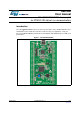
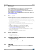
Figure 3. Top layout
1. Pin 1 of CN2, CN3, P1 and P2 connectors are identified by a square.
MS32777V1
(red/green LED) LD2
COM
CN3
SWD connector
IDD measurement
ST-LINK/V2
B1 user button
B2 reset button
LD1 (red LED)
PWR
CN2
ST-LINK/DISCOVERY
selector
(green LED) LD3
LD4 (blue LED)
STM32L100RCT6
JP2
5V power supply
input/output
3V power supply
su
input/output
SB1 (VBAT)
SB3 (B1-USER)
SB4 (B2-RESET)
VLCD
GND
VDD
VDD
GND
MB1108 rev B
STM32L100C-DISCO
PH0
PH1
www.st.com/stm32l1-discovery