
Datasheet


DocID022691 Rev 4 91/131
STM32F37xxx Electrical characteristics
114
6.3.16 Communications interfaces
I
2
C interface
characteristics
The I
2
C interface meets the requirements of the standard I
2
C communication protocol with
the following restrictions: the I/O pins SDA and SCL are mapped to are not “true” open-
drain. When configured as open-drain, the PMOS connected between the I/O pin and V
DD
is
disabled, but is still present.
The I
2
C characteristics are described in Table 56. Refer also to
Section 6.3.14: I/O port
characteristics
for more details on the input/output alternate function characteristics (SDA
and SCL)
.
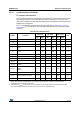
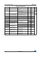
Table 56. I2C characteristics
(1)
Symbol Parameter
Standard Fast mode Fast mode +
Unit
Min Max Min Max Min Max
f
SCL
SCL clock frequency 0 100 0 400 0 1000 KHz
t
LOW
Low period of the SCL clock 4.7 - 1.3 - 0.5 - µs
t
HIGH
High Period of the SCL clock 4 - 0.6 - 0.26 - µs
tr
Rise time of both SDA and SCL
signals
- 1000 - 300 - 120 ns
tf
Fall time of both SDA and SCL
signals
- 300 - 300 - 120 ns
t
HD;DAT
Data hold time 0 - 0 - 0 - µs
t
VD;DAT
Data valid time - 3.45
(2)
-0.9
(2)
-0.45
(2)
µs
t
VD;ACK
Data valid acknowledge time - 3.45
(2)
-0.9
(2)
-0.45
(2)
µs
t
SU;DAT
Data setup time 250 - 100 - 50 - ns
t
HD;STA
Hold time (repeated) START
condition
4.0 - 0.6 - 0.26 - µs
t
SU;STA
Set-up time for a repeated
START
condition
4.7 - 0.6 - 0.26 - µs
t
SU;STO
Set-up time for STOP condition 4.0 - 0.6 - 0.26 - µs
t
BUF
Bus free time between a
STOP and START condition
4.7 - 1.3 - 0.5 - µs
C
b
Capacitive load for each bus line - 400 - 400 - 550 pF
1. The I2C characteristics are the requirements from the I2C bus specification rev03. They are guaranteed by
design when the I2Cx_TIMING register is correctly programmed (refer to reference manual). These
characteristics are not tested in production.
2. The maximum t
HD;DAT
could be 3.45 µs, 0.9 µs and 0.45 µs for standard mode, fast mode and fast mode
plus, but must be less than the maximum of t
VD;DAT
or t
VD;ACK
by a transition time.