
Datasheet

DocID022691 Rev 4 75/131
STM32F37xxx Electrical characteristics
114
For C
L1
and C
L2
, it is recommended to use high-quality external ceramic capacitors in the
5 pF to 20 pF range (typ.), designed for high-frequency applications, and selected to match
the requirements of the crystal or resonator (see Figure 14). C
L1
and C
L2
are usually the
same size. The crystal manufacturer typically specifies a load capacitance which is the
series combination of C
L1
and C
L2
. PCB and MCU pin capacitance must be included (10 pF
can be used as a rough estimate of the combined pin and board capacitance) when sizing
C
L1
and C
L2
.
Note: For information on electing the crystal, refer to the application note AN2867 “Oscillator
design guide for ST microcontrollers” available from the ST website www.st.com.
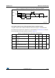
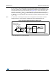
Figure 14. Typical application with an 8 MHz crystal
1. R
EXT
value depends on the crystal characteristics.
MS19876V1
OSC_OU T
OSC_IN
f
HSE
C
L1
R
F
8 MHz
resonator
R
EXT
(1)
C
L2
Resonator with
integrated capacitors
Bias
controlled
gain