
Datasheet

Electrical characteristics STM32F37xxx
74/131 DocID022691 Rev 4
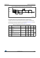
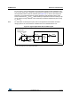
Figure 13. Low-speed external clock source AC timing diagram
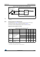
High-speed external clock generated from a crystal/ceramic resonator
The high-speed external (HSE) clock can be supplied with a 4 to 32 MHz crystal/ceramic
resonator oscillator. All the information given in this paragraph are based on design
simulation results obtained with typical external components specified in Table 40. In the
application, the resonator and the load capacitors have to be placed as close as possible to
the oscillator pins in order to minimize output distortion and startup stabilization time. Refer
to the crystal resonator manufacturer for more details on the resonator characteristics
(frequency, package, accuracy).
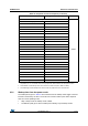
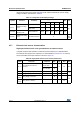
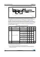
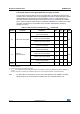
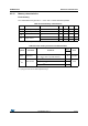
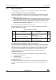
Table 40. HSE oscillator characteristics
Symbol Parameter Conditions
(1)
1. Resonator characteristics given by the crystal/ceramic resonator manufacturer.
Min
(2)
Typ Max
(2)
2. Guaranteed by design, not tested in production.
Unit
f
OSC_IN
Oscillator frequency 4 8 32 MHz
R
F
Feedback resistor - 200 - kΩ
I
DD
HSE current consumption
During startup
(3)
3. This consumption level occurs during the first 2/3 of the t
SU(HSE)
startup time
--8.5
mA
V
DD
= 3.3 V, Rm= 30 Ω,
CL= 10 pF@8 MHz
-0.4-
V
DD
= 3.3 V, Rm= 45 Ω,
CL= 10 pF@8 MHz
-0.5-
V
DD
= 3.3 V, Rm= 30 Ω,
CL=5 pF@32 MHz
-0.8-
V
DD
= 3.3 V, Rm= 30 Ω,
CL= 10 pF@32 MHz
-1-
V
DD
= 3.3 V, Rm= 30 Ω,
CL= 20 pF@32 MHz
-1.5-
g
m
Oscillator transconductance Startup 10 - - mA/V
t
SU(HSE)
(4)
4. t
SU(HSE)
is the startup time measured from the moment it is enabled (by software) to a stabilized 8 MHz
oscillation is reached. This value is measured for a standard crystal resonator and it can vary significantly
with the crystal manufacturer
Startup time V
DD
is stabilized - 2 - ms
MS19215V2
V
LSEH
t
f(LSE)
90%
10%
T
LSE
t
t
r(LSE)
V
LSEL
t
W(LSEH)
t
W(LSEL)