
Datasheet

DocID022691 Rev 4 83/131
STM32F37xxx Electrical characteristics
114
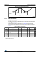
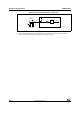
Note: It is recommended to add a Schottky diode (pin to ground) to analog pins which may
potentially inject negative currents.
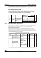
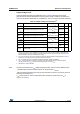
Table 51. I/O current injection susceptibility
Symbol Description
Functional
susceptibility
Unit
Negative
injection
Positive
injection
I
INJ
Injected current on BOOT0 pin -0 NA
mA
Injected current on PC0 pin -0 +5
Injected current on TC type I/O pins on VDDSD12 power
domain: PB2, PE7, PE8, PE9, PE10, PE11, PE12, PE13,
PE14, PE15, PB10 with induced leakage current on other pins
from this group less than -50 µA
-5 +5
Injected current on TC type I/O pins on VDDSD3 power
domain: PB14, PB15, PD8, PD9, PD10, PD12, PD13, PD14,
PD15 with induced leakage current on other pins from this
group less than -50 µA
-5 +5
Injected current on TTa type pins: PA4, PA5, PA6 with induced
leakage current on adjacent pins less than -10 µA
-5 +5
Injected current on any other FT and FTf pins -5 NA
Injected current on any other pins -5 +5