
Datasheet

Electrical characteristics STM32F37xxx
64/131 DocID022691 Rev 4
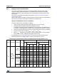
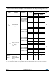
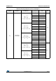
Table 31. Typical and maximum V
DDA
consumption in Stop and Standby modes
Symbol Parameter Conditions
Typ@V
DD
(V
DD
=V
DDA
)Max
(1)
Unit
2.0 V2.4 V2.7 V3.0 V3.3 V3.6 V
T
A
=
25 °C
T
A
=
85 °C
T
A
=
105 °C
I
DDA
Supply
current in
Stop mode
V
DDA
and V
DDSD12
Regulator in
run mode, all
oscillators OFF
1.99 2.07 2.19 2.33 2.46 2.64 10.8 11.8 12.4
µA
Regulator in
low-power
mode, all
oscillators OFF
1.99 2.07 2.18 2.32 2.47 2.63 10.6 11.5 12.5
Supply
current in
Standby
mode
LSI ON and
IWDG ON
2.44 2.53 2.7 2.89 3.09 3.33 - - -
LSI OFF and
IWDG OFF
1.87 1.94 2.06 2.19 2.35 2.51 4.1 4.5 4.8
IDDAmon
Supply
current for
V
DDA
and
V
DDSD12
monitoring
0.95 1.02 1.12 1.2 1.27 1.4 - - -
1. Data based on characterization results and tested in production.
2. To obtain data with monitoring OFF is necessary to substract the IDDAmon current.
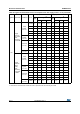
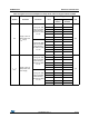
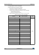
Table 32. Typical and maximum current consumption from V
BAT
supply
(1)
Symbol Parameter Conditions
Typ @ V
BAT
Max
(2)
Unit
= 1.65 V
= 1.8 V
= 2.0 V
= 2.4 V
= 2.7 V
= 3.3 V
= 3.6 V
T
A
=
25 °C
T
A
=
85 °C
T
A
=
105 °C
I
DD_
VBAT
Backup
domain
supply
current
LSE & RTC ON;
"Xtal mode" lower
driving capability;
LSEDRV[1:0] = '00'
0.50 0.52 0.55 0.63 0.70 0.87 0.95 1.1 1.6 2.2
µA
LSE & RTC ON;
"Xtal mode" higher
driving capability;
LSEDRV[1:0] = '11'
0.85 0.90 0.93 1.02 1.10 1.27 1.38 1.6 2.4 3.0
1. Crystal used: Abracon ABS07-120-32.768kHz-T with 6 pF of CL for typical values.
2. Data based on characterization results, not tested in production.