
Datasheet
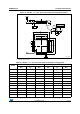
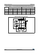

Package characteristics STM32F37xxx
124/131 DocID022691 Rev 4
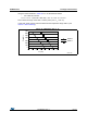
7.2.2 Selecting the product temperature range
When ordering the microcontroller, the temperature range is specified in the ordering
information scheme shown in Section 8: Part numbering.
Each temperature range suffix corresponds to a specific guaranteed ambient temperature at
maximum dissipation and, to a specific maximum junction temperature.
As applications do not commonly use the STM32F373x at maximum dissipation, it is useful
to calculate the exact power consumption and junction temperature to determine which
temperature range will be best suited to the application.
The following examples show how to calculate the temperature range needed for a given
application.
Example 1: High-performance application
Assuming the following application conditions:
Maximum ambient temperature T
Amax
= 82 °C (measured according to JESD51-2),
I
DDmax
= 50 mA, V
DD
= 3.5 V, maximum 3 I/Os used at the same time in output at low
level with I
OL
= 8 mA, V
OL
= 0.4 V and maximum 2 I/Os used at the same time in output
at low level with I
OL
= 20 mA, V
OL
= 1.3 V
P
INTmax
= 50 mA × 3.5 V= 175 mW
P
IOmax
= 3 × 8 mA × 0.4 V + 2 × 20 mA × 1.3 V = 61.6 mW
This gives: P
INTmax
= 175 mW and P
IOmax
= 61.6 mW:
P
Dmax
=
175
+
61.6 = 236.6 mW
Thus: P
Dmax
= 236.6 mW
Using the values obtained in Table 80 T
Jmax
is calculated as follows:
– For LQFP64, 45°C/W
T
Jmax
= 82 °C + (45°C/W × 236.6 mW) = 82 °C + 10.65 °C = 92.65 °C
This is within the range of the suffix 6 version parts (–40 < T
J
< 105 °C).
In this case, parts must be ordered at least with the temperature range suffix 6 (see
Section 8: Part numbering).
Example 2: High-temperature application
Using the same rules, it is possible to address applications that run at high ambient
temperatures with a low dissipation, as long as junction temperature T
J
remains within the
specified range.
Assuming the following application conditions:
Maximum ambient temperature T
Amax
= 115 °C (measured according to JESD51-2),
I
DDmax
= 20 mA, V
DD
= 3.5 V, maximum 9 I/Os used at the same time in output at low
level with I
OL
= 8 mA, V
OL
= 0.4 V
P
INTmax
=
20 mA × 3.5 V= 70 mW
P
IOmax
= 9 × 8 mA × 0.4 V = 28.8 mW
This gives: P
INTmax
= 70 mW and P
IOmax
= 28.8 mW:
P
Dmax
= 70
+
28.8 = 98.8 mW
Thus: P
Dmax
= 98.8 mW