STM32F313xx ARM Cortex-M4 32b MCU+FPU, up to 256KB Flash+48KB SRAM 4 ADCs, 2 DACs, 7 comp., 4 PGA, timers, 1.8 V operation Data brief Features ■ ■ ■ ■ ■ ■ ■ ■ ■ ■ ■ ■ ■ Core: ARM® 32-bit Cortex™-M4F CPU (72 MHz max), single-cycle multiplication and HW division, DSP instruction with FPU (floating-point unit) and MPU (memory protection unit). Operating conditions: – VDD: 1.8V +/- 8% – VDDA voltage range: 1.65 to 3.
Contents STM32F313xx Contents 1 Introduction . . . . . . . . . . . . . . . . . . . . . . . . . . . . . . . . . . . . . . . . . . . . . . . . 6 2 Description . . . . . . . . . . . . . . . . . . . . . . . . . . . . . . . . . . . . . . . . . . . . . . . . . 7 3 Functional overview . . . . . . . . . . . . . . . . . . . . . . . . . . . . . . . . . . . . . . . . 10 3.1 ARM® Cortex™-M4F core with embedded Flash and SRAM . . . . . . . . . 10 3.2 Memory protection unit . . . . . . . . . . . . . . . . . . .
STM32F313xx Contents 3.16.5 Window watchdog . . . . . . . . . . . . . . . . . . . . . . . . . . . . . . . . . . . . . . . . . 19 3.16.6 SysTick timer . . . . . . . . . . . . . . . . . . . . . . . . . . . . . . . . . . . . . . . . . . . . . 20 3.17 Real-time clock (RTC) and backup registers . . . . . . . . . . . . . . . . . . . . . . 21 3.18 I2C bus . . . . . . . . . . . . . . . . . . . . . . . . . . . . . . . . . . . . . . . . . . . . . . . . . . . 21 3.
List of tables STM32F313xx List of tables Table 1. Table 2. Table 3. Table 4. Table 5. Table 6. Table 7. Table 8. Table 9. Table 10. Table 11. Table 12. Table 13. Table 14. Table 15. Table 16. Table 17. Table 18. Table 19. Table 20. Table 21. Table 22. Table 23. Table 24. Table 25. Table 26. 4/58 Device summary . . . . . . . . . . . . . . . . . . . . . . . . . . . . . . . . . . . . . . . . . . . . . . . . . . . . . . . . . . 1 STM32F31x family device features and peripheral counts . . . . . . . . . . .
STM32F313xx List of figures List of figures Figure 1. Figure 2. Figure 3. Figure 4. Figure 5. Figure 6. Figure 7. Figure 8. Figure 9. Figure 10. Figure 11. Figure 12. Figure 13. Figure 14. STM32F313xx block diagram . . . . . . . . . . . . . . . . . . . . . . . . . . . . . . . . . . . . . . . . . . . . . . . . 9 Clock tree . . . . . . . . . . . . . . . . . . . . . . . . . . . . . . . . . . . . . . . . . . . . . . . . . . . . . . . . . . . . . . 13 Infrared transmitter . . . . . . . . . . . . . . . . . . .
Introduction 1 STM32F313xx Introduction This databrief provides the ordering information and mechanical device characteristics of the STM32F31x microcontrollers. This STM32F31x databrief should be read in conjunction with the STM32F31x reference manual. The reference manual is available from the STMicroelectronics website www.st.com. For information on the Cortex™-M4F core please refer to the Cortex™-M4F Technical Reference Manual, available from the www.arm.
STM32F313xx 2 Description Description The STM32F313xx family is based on the high-performance ARM® Cortex™-M4 32-bit RISC core operating at a frequency of up to 72 MHz, and embedding a floating point unit (FPU), a memory protection unit (MPU) and an embedded trace macrocell (ETM). The family incorporates high-speed embedded memories (up to 256 Kbytes of Flash memory, up to 48 Kbytes of SRAM), and an extensive range of enhanced I/Os and peripherals connected to two APB buses.
Description STM32F313xx Table 2. STM32F31x family device features and peripheral counts STM32F 313Cx Peripheral STM32F 313Rx STM32F 313Vx Flash (Kbytes) 128 256 128 256 128 256 SRAM (Kbytes) on data bus 32 40 32 40 32 40 SRAM (Kbytes) on instruction bus (CCM: core coupled memory) Timers Advanced control 2 (16-bit) General purpose 5 (16-bit) 1 (32 bit) Basic 2 (16-bit) SPI(I2S) Comm.
STM32F313xx STM32F313xx block diagram TPIU ETM SWJTAG Trace/Trig OBL VDD18 MPU/FPU Ibus Cortex M4 CPU Flash interface TRADECLK TRACED[0-3] as AF JTRST JTDI JTCK/SWCLK JTMS/SWDAT JTDO As AF Power System NVIC VDDIO = 1.8 +/- 8% VSS @VDDIO FLASH 256 KB 64 bits NRESET VDDA VSSA NPOR Dbus Fmax: 72 MHz CCM RAM 8KB BusMatrix Figure 1.
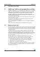
Functional overview STM32F313xx 3 Functional overview 3.1 ARM® Cortex™-M4F core with embedded Flash and SRAM The ARM Cortex-M4F processor is the latest generation of ARM processors for embedded systems. It was developed to provide a low-cost platform that meets the needs of MCU implementation, with a reduced pin count and low-power consumption, while delivering outstanding computational performance and an advanced response to interrupts.
STM32F313xx 3.3 Functional overview Embedded Flash memory All STM32F313xx devices feature up to 256 Kbytes of embedded Flash memory available for storing programs and data. The Flash memory access time is adjusted to the CPU clock frequency (0 wait state from 0 to 24 MHz, 1 wait state from 24 to 48 MHz and 2 wait states above). 3.4 Embedded SRAM STM32F313xx devices feature up to 48 Kbytes of embedded SRAM with hardware parity check.
Functional overview STM32F313xx level must be always greater or equal to the VDD voltage level and must be provided first. ● 3.7.2 VBAT = 1.65 to 3.6 V: power supply for RTC, external clock 32 kHz oscillator and backup registers (through power switch) when VDD is not present. Power supply supervision The device power on reset is controlled through the external NPOR pin. The device remains in reset state when NPOR pin is held low.
STM32F313xx Figure 2. Functional overview Clock tree FLITFCLK to Flash programming interface HSI to I2Cx (x = 1,2) SYSCLK I2SSRC SYSCLK to I2Sx (x = 2,3) Ext. clock I2S_CKIN 8 MHz HSI HSI RC /2 HCLK PLLSRC PLLMUL PLL x2,x3,.. x16 SW HSI PLLCLK HSE /8 AHB AHB prescaler /1,2,..512 APB1 prescaler /1,2,4,8,16 SYSCLK OSC_OUT OSC_IN PCLK1 SYSCLK HSI LSE 4-32 MHz HSE OSC /32 OSC32_IN OSC32_OUT LSE OSC 32.768kHz APB2 prescaler /1,2,4,8,16 RTCCLK LSI Main clock output to USARTx (x = 2..
Functional overview 3.9 STM32F313xx GPIOs (general-purpose inputs/outputs) Each of the GPIO pins can be configured by software as output (push-pull or open-drain), as input (with or without pull-up or pull-down) or as peripheral alternate function. Most of the GPIO pins are shared with digital or analog alternate functions. All GPIOs are high current capable except for analog inputs.
STM32F313xx 3.12 Functional overview Fast ADC (analog-to-digital converter) Up to four fast analog-to-digital converters 5 MSPS, with selectable resolution between 12 and 6 bit, are embedded in the STM32F313xx family devices. The ADCs have up to 39 external channels. Some of the external channels are shared between ADC1&2 and between ADC3&4, performing conversions in single-shot or scan modes. In scan mode, automatic conversion is performed on a selected group of analog inputs.
Functional overview Table 3. STM32F313xx Temperature sensor calibration values Calibration value name 3.12.2 Description Memory address TS_CAL1 TS ADC raw data acquired at temperature of 30 °C, VDDA= 3.3 V 0x1FFF F7B8 - 0x1FFF F7B9 TS_CAL2 TS ADC raw data acquired at temperature of 110 °C VDDA= 3.3 V 0x1FFF F7C2 - 0x1FFF F7C3 Internal voltage reference (VREFINT) The internal voltage reference (VREFINT) provides a stable (bandgap) voltage output for the ADC and Comparators.
STM32F313xx Functional overview This digital interface supports the following features: 3.
Functional overview Table 5.
STM32F313xx 3.16.2 Functional overview General-purpose timers (TIM2, TIM3, TIM4, TIM15, TIM16, TIM17) There are up to six synchronizable general-purpose timers embedded in the STM32F313xx (see Table 5 for differences). Each general-purpose timer can be used to generate PWM outputs, or act as a simple time base.
Functional overview 3.16.6 STM32F313xx SysTick timer This timer is dedicated to real-time operating systems, but could also be used as a standard down counter. It features: 20/58 ● A 24-bit down counter ● Autoreload capability ● Maskable system interrupt generation when the counter reaches 0.
STM32F313xx 3.17 Functional overview Real-time clock (RTC) and backup registers The RTC and the 16 backup registers are supplied through a switch that takes power from either the VDD supply when present or the VBAT pin. The backup registers are sixteen 32-bit registers used to store 64 bytes of user application data when VDD power is not present. They are not reset by a system or power reset. The RTC is an independent BCD timer/counter.
Functional overview Table 6. STM32F313xx Comparison of I2C analog and digital filters Analog filter Digital filter Pulse width of suppressed spikes 50 ns Programmable length from 1 to 15 I2C peripheral clocks Benefits Available in Stop mode 1. Extra filtering capability vs. standard requirements. 2. Stable length Drawbacks Variations depending on temperature, voltage, process Disabled when Wakeup from Stop mode is enabled In addition, they provide hardware support for SMBUS 2.0 and PMBUS 1.
STM32F313xx 3.20 Functional overview Universal asynchronous receiver transmitter (UART) The STM32F313xx devices have 2 embedded universal asynchronous receiver transmitters (UART4, and UART5). The UART interfaces support IrDA SIR ENDEC, multiprocessor communication mode and single-wire half-duplex communication mode. The UART interfaces can be served by the DMA controller. Refer to Table 8 for the features available in all U(S)ARTs interfaces Table 8.
Functional overview Table 9. STM32F313xx STM32F31x SPI/I2S implementation SPI features(1) SPI1 SPI2 SPI3 Hardware CRC calculation X X X Rx/Tx FIFO X X X NSS pulse mode X X X X X X X I2S mode TI mode X 1. X = supported. 3.22 Controller area network (CAN) The CAN is compliant with specifications 2.0A and B (active) with a bit rate up to 1 Mbit/s. It can receive and transmit standard frames with 11-bit identifiers as well as extended frames with 29-bit identifiers.
STM32F313xx Functional overview variation introduced by the finger (or any conductive object) is measured using a proven implementation based on a surface charge transfer acquisition principle. It consists of charging the electrode capacitance and then transferring a part of the accumulated charges into a sampling capacitor until the voltage across this capacitor has reached a specific threshold.
Functional overview STM32F313xx Table 10.
STM32F313xx Functional overview 3.25 Development support 3.25.1 Serial wire JTAG debug port (SWJ-DP) The ARM SWJ-DP Interface is embedded, and is a combined JTAG and serial wire debug port that enables either a serial wire debug or a JTAG probe to be connected to the target. The JTAG TMS and TCK pins are shared respectively with SWDIO and SWCLK and a specific sequence on the TMS pin is used to switch between JTAG-DP and SW-DP. 3.25.
Pinouts and pin description STM32F313xx Pinouts and pin description Figure 4.
STM32F313xx PA14 PA15 PC10 PC11 PC12 PD2 PB3 PB4 PB5 PB6 PB7 BOOT0 PB8 VSS_1 PB9 VDD_1 STM32F313xx LQFP64 pinout 64 63 62 61 60 59 58 57 56 55 54 53 52 51 50 49 VBAT 1 48 VDD_3 PC13 2 47 VSS_3 PC14 / OSC32_IN 3 46 PA13 PC15 / OSC32_OUT 4 45 PA12 PF0 / OSC_IN 5 PF1 / OSC_OUT 6 44 PA11 43 PA10 NRST 7 PC0 8 42 PA9 PC1 9 40 PC9 PC2 10 39 PC8 41 PA8 64-pins PC3 11 38 PC7 VSSA 12 37 PC6 VDDA 13 36 PB15 14 35 PB14 PA1 15 34 PB13 PA0 PA2 16 33 PB12 VDD_2 PB1
Pinouts and pin description 0! 0! 0# 0# 0# 0$ 0$ 0$ 0$ 0$ 0$ 0$ 0$ 0" 0" 0" 0" 0" "//4 0" 0" 0% 633? 0% STM32F313xx LQFP100 pinout 6$$? Figure 6. STM32F313xx 0% 6$$? 0% 633? 0% 0& 0% 0! 0% 6"!4 0! 0! 0# 0! 0# /3# ?).
STM32F313xx Pinouts and pin description Table 12. Legend/abbreviations used in the pinout table Name Pin name Pin type Abbreviation Definition Unless otherwise specified in brackets below the pin name, the pin function during and after reset is the same as the actual pin name S Supply pin I Input only pin I/O Input / output pin FT 5 V tolerant I/O FTf 5 V tolerant I/O, FM+ capable TTa 3.3 V tolerant I/O directly connected to ADC TC Standard 3.
Pinouts and pin description Pin name (function after reset) I/O structure Notes STM32F313xx pin definitions Pin type Table 13.
STM32F313xx LQF P100 LQF P64 LQF P48 Pin name (function after reset) Pin functions Notes Pin number I/O structure STM32F313xx pin definitions (continued) Pin type Table 13.
Pinouts and pin description LQF P100 LQF P64 34 25 LQF P48 Pin name (function after reset) Notes Pin number I/O structure STM32F313xx pin definitions (continued) Pin type Table 13.
STM32F313xx Pin name (function after reset) I/O structure Notes STM32F313xx pin definitions (continued) Pin type Table 13.
Pinouts and pin description LQF P100 LQF P64 LQF P48 73 Pin name (function after reset) Notes Pin number I/O structure STM32F313xx pin definitions (continued) Pin type Table 13.
STM32F313xx LQF P100 91 92 LQF P64 57 58 LQF P48 41 42 Pin name (function after reset) PB5 PB6 I/O I/O FTf I2C1_SCL, USART1_TX, TIM16_CH1N, TIM4_CH1, TIM8_CH1(3), TSC_G5_IO3, TIM8_ETR, TIM8_BKIN2(3) I2C1_SDA, USART1_RX, TIM3_CH4, TIM4_CH2, TIM17_CH1N, TIM8_BKIN, TSC_G5_IO4 43 PB7 I/O FTf 94 60 44 BOOT0 I B 96 62 45 46 PB8 I/O Additional functions FT 59 61 Alternate functions SPI3_MOSI, SPI1_MOSI, I2S3_SD, I2C1_SMBA, USART2_CK, TIM16_BKIN, TIM3_CH2, TIM8_CH3N(3), TIM17_CH
Doc ID 023636 Rev 1 AF n° Port & Pin Name 7 PA0 TIM2_ CH1_ ETR 5 PA1 6 5 AF0 AF1 AF2 AF4 AF5 TSC_ G1_IO1 USART2 COMP1 TIM8_ _CTS _OUT BKIN TM8_ ETR TIM2_ CH2 TSC_ G1_IO2 USART2 _RTS TIM15_ CH1N EVENT OUT PA2 TIM2_ CH3 TSC_ G1_IO3 USART2 COMP2 TIM15_ _TX _OUT CH1 EVENT OUT PA3 TIM2_ CH4 TSC_ G1_IO4 USART2 _RX EVENT OUT SPI1_ NSS SPI1_ SCK SPI3_ NSS/ I2S3_ WS AF7 AF8 AF11 AF12 AF15 AF10 TSC_ G2_IO1 AF6 AF14 AF9 TIM3_ CH2 AF3 AF13 Alternate functions for port A
AF n° Port & Pin Name 9 PA12 7 PA13 JTMSSWDAT 7 PA14 JTCKSWCLK 9 PA15 AF0 AF1 AF2 AF3 AF4 AF5 TIM16_ CH1 JTDI TIM1_ CH2N TIM16_ CH1N Doc ID 023636 Rev 1 TIM2_ CH1_ ETR AF6 TIM8_ CH1 AF7 AF8 AF9 AF10 AF11 AF12 AF13 Alternate functions for port A AF14 AF15 USART1 COMP2 TIM4_ TIM1_ CAN_TX _RTS _OUT CH2 ETR EVENT OUT USART3 _CTS EVENT OUT TSC_ G4_IO3 IR-Out TSC_ I2C1_ G4_IO4 SDA TIM8_ CH2 TIM1_ BKIN USART2 _TX I2C1_ SCL SPI1_ NSS SPI3_ NSS/ I2S3_ WS USART2 _RX T
Alternate functions for port B Port & AF n° Pin Name AF0 AF1 AF2 AF3 AF4 AF5 AF6 AF7 AF8 AF9 AF10 AF12 AF15 Doc ID 023636 Rev 1 5 PB0 TIM3_ CH3 TSC_ TIM8_ G3_IO2 CH2N TIM1_CH2N 6 PB1 TIM3_ CH4 TSC_ TIM8_ G3_IO3 CH3N TIM1_CH3N 10 PB3 JTDO/ TRACE SWO TIM2_ CH2 TIM4_ ETR TSC_ TIM8_ G5_IO1 CH1N SPI1_ SCK SPI3_SCK /I2S3_CK 10 PB4 NJTRST TIM16_ TIM3_ CH1 CH1 TSC_ TIM8_ G5_IO2 CH2N SPI1_ MISO 9 PB5 TIM16_ TIM3_ BKIN CH2 TIM8_ CH3N SPI1_ MOSI 9 PB6 TIM16_ TIM4_ CH1N CH
Alternate functions for port B Port & AF n° Pin Name AF0 AF1 AF2 6 PB14 TIM15_ CH1 5 PB15 TIM15_ TIM15 CH2 _CH1N AF3 AF4 TSC_ G6_IO4 AF5 AF6 SPI2_MISO/ TIM1_ I2S2ext_SD CH2N TIM1_ CH3N SPI2_MOSI/ I2S2_SD AF7 USART3_ RTS AF8 AF9 AF10 AF12 AF15 STM32F313xx Table 15.
Alternate functions for port C Doc ID 023636 Rev 1 AF n° Port & Pin Name 1 PC0 EVENTOUT 1 PC1 EVENTOUT 2 PC3 EVENTOUT 2 PC4 EVENTOUT 3 PC5 EVENTOUT 5 PC6 EVENTOUT TIM3_CH1 TIM8_CH1 I2S2_MCK COMP6_OUT 5 PC7 EVENTOUT TIM3_CH2 TIM8_CH2 I2S3_MCK COMP5_OUT 4 PC8 EVENTOUT TIM3_CH3 TIM8_CH3 5 PC9 EVENTOUT TIM3_CH4 TIM8_CH4 I2S_CKIN TIM8_BKIN2 5 PC10 EVENTOUT TIM8_CH1N UART4_TX SPI3_SCK/I2S3_CK USART3_TX 5 PC11 EVENTOUT TIM8_CH2N UART4_RX SPI3_MISO/I2S3ext_SD
AF n° Alternate functions for port D Port & Pin Name AF1 AF2 AF3 AF1 AF5 AF6 AF7 Doc ID 023636 Rev 1 2 PD0 EVENTOUT CAN_RX 4 PD1 EVENTOUT 3 PD3 EVENTOUT TIM2_CH1_ETR USART2_CTS 3 PD4 EVENTOUT TIM2_CH2 USART2_RTS 2 PD5 EVENTOUT 3 PD6 EVENTOUT TIM2_CH4 USART2_RX 3 PD7 EVENTOUT TIM2_CH3 USART2_CK 2 PD8 EVENTOUT USART3_TX 2 PD9 EVENTOUT USART3_RX 2 PD10 EVENTOUT USART3_CK 2 PD11 EVENTOUT USART3_CTS 4 PD12 EVENTOUT TIM4_CH1 TSC_G8_IO1 3 PD13 EVENTOUT
AF n° Alternate functions for port E Port & Pin Name AF0 AF1 AF2 TIM4_ETR AF3 Doc ID 023636 Rev 1 4 PE0 EVENTOUT 3 PE1 EVENTOUT 4 PE3 TRACED0 EVENTOUT TIM3_CH2 TSC_G7_IO2 4 PE4 TRACED1 EVENTOUT TIM3_CH3 TSC_G7_IO3 4 PE5 TRACED2 EVENTOUT TIM3_CH4 TSC_G7_IO4 2 PE6 TRACED3 EVENTOUT 2 PE7 EVENTOUT TIM1_ETR 2 PE8 EVENTOUT TIM1_CH1N 2 PE9 EVENTOUT TIM1_CH1 2 PE10 EVENTOUT TIM1_CH2N 2 PE11 EVENTOUT TIM1_CH2 2 PE12 EVENTOUT TIM1_CH3N 2 PE13 EVENTOUT TIM1
AF n° Alternate functions for port F Port & Pin Name AF1 AF2 AF3 AF4 AF5 2 PF0 I2C2_SDA 1 PF1 I2C2_SCL 2 PF4 EVENTOUT COMP1_OUT 4 PF6 EVENTOUT TIM4_CH4 3 PF9 EVENTOUT TIM15_CH1 SPI2_SCK 3 PF10 EVENTOUT TIM15_CH2 SPI2_SCK AF6 AF7 TIM1_CH3N I2C2_SCL STM32F313xx Table 19.
Memory mapping STM32F313xx 5 Memory mapping Figure 7.
STM32F313xx Memory mapping Table 20.
Memory mapping Table 20.
STM32F313xx Package characteristics 6 Package characteristics 6.1 Package mechanical data In order to meet environmental requirements, ST offers these devices in different grades of ECOPACK® packages, depending on their level of environmental compliance. ECOPACK® specifications, grade definitions and product status are available at: www.st.com. ECOPACK® is an ST trademark.
Package characteristics Figure 8. STM32F313xx LQFP100, 14 x 14 mm, 100-pin low-profile quad flat package outline(1) Recommended footprint(1)(2) Figure 9. 0.25 mm 0.10 inch GAGE PLANE 75 k 51 D L D1 76 50 0.5 L1 D3 51 75 C 0.3 76 50 16.7 14.3 b E3 E1 E 100 26 1.2 1 100 25 26 Pin 1 1 identification 25 ccc 12.3 C 16.7 e A1 ai14906 A2 A SEATING PLANE C 1L_ME 1. Drawing is not to scale. 2. Dimensions are in millimeters. Table 21.
STM32F313xx Package characteristics Figure 10. LQFP64 – 10 x 10 mm, 64 pin low-profile quad flat package outline(1) Figure 11. Recommended footprint(1)(2) D 48 33 ccc C D1 33 48 0.3 A A2 D3 49 32 0.5 32 49 12.7 10.3 b L1 10.3 E3 E1 E 64 1.2 L A1 17 K 1 16 64 7.8 17 Pin 1 identification 16 1 12.7 c 5W_ME ai14909 1. Drawing is not to scale. 2. Dimensions are in millimeters. Table 22.
Package characteristics STM32F313xx Figure 12. LQFP48 – 7 x 7mm, 48-pin low-profile quad flat package outline(1) Figure 13. Recommended footprint(1)(2) D 0.50 1.20 ccc C D1 D3 A A2 0.30 25 36 37 24 25 36 24 37 9.70 0.20 7.30 5.80 L1 b 7.30 E3 E1 E 48 13 12 1 1.20 48 Pin 1 identification 13 1 12 A1 L 5.80 K 9.70 c ai14911b 5B_ME 1. Drawing is not to scale. 2. Dimensions are in millimeters. Table 23.
STM32F313xx 6.2 Package characteristics Thermal characteristics The maximum chip-junction temperature, TJ max, in degrees Celsius, may be calculated using the following equation: TJ max = TA max + (PD max x JA) Where: ● TA max is the maximum ambient temperature in C, ● JA is the package junction-to-ambient thermal resistance, in C/W, ● PD max is the sum of PINT max and PI/O max (PD max = PINT max + PI/Omax), ● PINT max is the product of IDD and VDD, expressed in Watts.
Package characteristics 6.2.2 STM32F313xx Selecting the product temperature range When ordering the microcontroller, the temperature range is specified in the ordering information scheme shown in Table 25: Ordering information scheme. Each temperature range suffix corresponds to a specific guaranteed ambient temperature at maximum dissipation and, to a specific maximum junction temperature.
STM32F313xx Package characteristics Using the values obtained in Table 24 TJmax is calculated as follows: – For LQFP100, 46 °C/W TJmax = 115 °C + (46 °C/W × 134 mW) = 115 °C + 6.2 °C = 121.2 °C This is within the range of the suffix 7 version parts (–40 < TJ < 125 °C). In this case, parts must be ordered at least with the temperature range suffix 7 (see Table 25: Ordering information scheme). Figure 14. LQFP100 PD max vs.
Part numbering STM32F313xx 7 Part numbering Table 25.
STM32F313xx 8 Revision history Revision history Table 26. Document revision history Date Revision 07-Sep-2012 1 Changes Initial release.
STM32F313xx Please Read Carefully: Information in this document is provided solely in connection with ST products. STMicroelectronics NV and its subsidiaries (“ST”) reserve the right to make changes, corrections, modifications or improvements, to this document, and the products and services described herein at any time, without notice. All ST products are sold pursuant to ST’s terms and conditions of sale.