
Datasheet


Electrical characteristics STM32F21xxx
70/175 DocID17050 Rev 9
V
DD
= 2.4 to
2.7 V
Conversion
time up to
2Msps
24 MHz with
no Flash
memory wait
state
4
(2)
– Degraded
speed
performance
–I/O
compensation
works
up to 48 MHz
16-bit erase
and program
operations
V
DD
= 2.7 to
3.6 V
(3)
Conversion
time up to
2Msps
30 MHz with
no Flash
memory wait
state
3
(2)
– Full-speed
operation
–I/O
compensation
works
–up to
60 MHz
when V
DD
=
3.0 to 3.6 V
–up to
48 MHz
when V
DD
=
2.7 to 3.0 V
32-bit erase
and program
operations
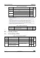
1. The number of wait states can be reduced by reducing the CPU frequency (see Figure 19).
2. Thanks to the ART accelerator and the 128-bit Flash memory, the number of wait states given here does not impact the
execution speed from Flash memory since the ART accelerator allows to achieve a performance equivalent to 0 wait state
program execution.
3. The voltage range for OTG USB FS can drop down to 2.7 V. However it is degraded between 2.7 and 3 V.
Table 14. Limitations depending on the operating power supply range (continued)
Operating
power
supply
range
ADC
operation
Maximum
Flash
memory
access
frequency
(f
Flashmax
)
Number of wait
states at
maximum CPU
frequency
(f
CPUmax
=
120 MHz)
(1)
I/O operation
FSMC_CLK
frequency for
synchronous
accesses
Possible
Flash
memory
operations