
Datasheet


DocID17050 Rev 9 69/175
STM32F21xxx Electrical characteristics
174
V
BAT
Backup operating voltage 1.65 3.6
V
V
IN
I/O input voltage
FT and TTa I/O TBD TBD
BOOT0 TBD TBD
V
CAP1
Internal core voltage to be supplied
externally in REGOFF mode
1.1 1.3 V
V
CAP2
P
D
Power dissipation at T
A
= 85 °C for
suffix 6 or T
A
= 105 °C for suffix 7
(4)
LQFP64 - 444
mW
LQFP100 - 434
LQFP144 - 500
LQFP176 - 526
UFBGA176 - 513
T
A
Ambient temperature for 6 suffix
version
Maximum power dissipation –40 85
°C
Low power dissipation
(5)
–40 105
Ambient temperature for 7 suffix
version
Maximum power dissipation –40 105
°C
Low power dissipation
(5)
–40 125
T
J Junction temperature range
6 suffix version –40 105
°C
7 suffix version –40 125
1. TBD stands for “to be defined”.
2. When the ADC is used, refer to Table 65: ADC characteristics.
3. It is recommended to power V
DD
and V
DDA
from the same source. A maximum difference of 300 mV between V
DD
and
V
DDA
can be tolerated during power-up and power-down operation.
4. If T
A
is lower, higher P
D
values are allowed as long as T
J
does not exceed T
Jmax
.
5. In low power dissipation state, T
A
can be extended to this range as long as T
J
does not exceed T
Jmax
.
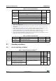
Table 13. General operating conditions
(1)
(continued)
Symbol Parameter Conditions Min Max Unit
Table 14. Limitations depending on the operating power supply range
Operating
power
supply
range
ADC
operation
Maximum
Flash
memory
access
frequency
(f
Flashmax
)
Number of wait
states at
maximum CPU
frequency
(f
CPUmax
=
120 MHz)
(1)
I/O operation
FSMC_CLK
frequency for
synchronous
accesses
Possible
Flash
memory
operations
V
DD
=1.8 to
2.1 V
Conversion
time up to
1Msps
16 MHz with
no Flash
memory wait
state
7
(2)
– Degraded
speed
performance
– No I/O
compensation
up to 30 MHz
8-bit erase
and program
operations
only
V
DD
= 2.1 to
2.4 V
Conversion
time up to
1Msps
18 MHz with
no Flash
memory wait
state
6
(2)
– Degraded
speed
performance
– No I/O
compensation
up to 30 MHz
16-bit erase
and program
operations