
Datasheet


DocID17050 Rev 9 139/175
STM32F21xxx Electrical characteristics
174
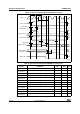
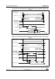
PC Card/CompactFlash controller waveforms and timings
Figure 62 through Figure 67 represent synchronous waveforms together with Table 79 and
Table 80 provides the corresponding timings. The results shown in this table are obtained
with the following FSMC configuration:
• COM.FSMC_SetupTime = 0x04;
• COM.FSMC_WaitSetupTime = 0x07;
• COM.FSMC_HoldSetupTime = 0x04;
• COM.FSMC_HiZSetupTime = 0x00;
• ATT.FSMC_SetupTime = 0x04;
• ATT.FSMC_WaitSetupTime = 0x07;
• ATT.FSMC_HoldSetupTime = 0x04;
• ATT.FSMC_HiZSetupTime = 0x00;
• IO.FSMC_SetupTime = 0x04;
• IO.FSMC_WaitSetupTime = 0x07;
• IO.FSMC_HoldSetupTime = 0x04;
• IO.FSMC_HiZSetupTime = 0x00;
• TCLRSetupTime = 0;
• TARSetupTime = 0;
In all timing tables, the
T
HCLK
is the HCLK clock period.
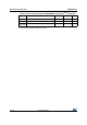
t
d(CLKL-Data)
FSMC_D[15:0] valid data after FSMC_CLK low - 2 ns
t
d(CLKL-NBLH)
FSMC_CLK low to FSMC_NBL high 2 - ns
1. C
L
= 30 pF.
2. Based on characterization, not tested in production.
Table 78. Synchronous non-multiplexed PSRAM write timings
(1)(2)
(continued)
Symbol Parameter Min Max Unit