
Datasheet


Electrical characteristics STM32F21xxx
124/175 DocID17050 Rev 9
General PCB design guidelines
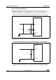
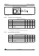
Power supply decoupling should be performed as shown in Figure 51 or Figure 52,
depending on whether V
REF+
is connected to V
DDA
or not. The 10 nF capacitors should be
ceramic (good quality). They should be placed them as close as possible to the chip.
Figure 51. Power supply and reference decoupling (V
REF+
not connected to V
DDA
)
1. V
REF+
and V
REF–
inputs are both available on UFBGA176 package. V
REF+
is also available on all packages
except for LQFP64. When V
REF+
and V
REF–
are not available, they are internally connected to V
DDA
and
V
SSA
.
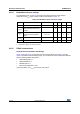
Figure 52. Power supply and reference decoupling (V
REF+
connected to V
DDA
)
1. V
REF+
and V
REF–
inputs are both available on UFBGA176 package. V
REF+
is also available on all packages
except for LQFP64. When V
REF+
and V
REF–
are not available, they are internally connected to V
DDA
and
V
SSA
.
V
REF+
STM32F
V
DDA
V
SSA
/V
REF-
1 µF // 10 nF
1 µF // 10 nF
ai17535
(See note 1)
(See note 1)
V
REF+
/V
DDA
STM32F
1 µF // 10 nF
V
REF–
/V
SSA
ai17536
(See note 1)
(See note 1)