
Datasheet


Electrical characteristics STM32F21xxx
118/175 DocID17050 Rev 9
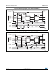
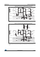
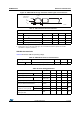
Figure 45. ULPI timing diagram
Ethernet characteristics
Table 61 shows the Ethernet operating voltage.
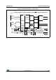
Table 62 gives the list of Ethernet MAC signals for the SMI (station management interface)
and Figure 46 shows the corresponding timing diagram.
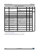
Table 60. ULPI timing
Symbol Parameter
Value
(1)
1. V
DD
= 2.7 V to 3.6 V and T
A
= –40 to 85 °C.
Unit
Min. Max.
t
SC
Control in (ULPI_DIR) setup time - 2.0
ns
Control in (ULPI_NXT) setup time - 1.5
t
HC
Control in (ULPI_DIR, ULPI_NXT) hold time 0 -
t
SD
Data in setup time - 2.0
t
HD
Data in hold time 0 -
t
DC
Control out (ULPI_STP) setup time and hold time - 9.2
t
DD
Data out available from clock rising edge - 10.7
Table 61. Ethernet DC electrical characteristics
Symbol Parameter Min.
(1)
1. All the voltages are measured from the local ground potential.
Max.
(1)
Unit
Input level V
DD
Ethernet operating voltage 2.7 3.6 V
Clock
Control In
(ULPI_DIR,
ULPI_NXT)
data In
(8-bit)
Control out
(ULPI_STP)
data out
(8-bit)
t
DD
t
DC
t
HD
t
SD
t
HC
t
SC
ai17361c
t
DC