
Datasheet


Revision history STM32F20xxx
168/178 DocID15818 Rev 11
22-Apr-2011 6
Changed datasheet status to “Full Datasheet”.
Introduced concept of SRAM1 and SRAM2.
LQFP176 package now in production and offered only for 256 Kbyte
and 1 Mbyte devices. Availability of WLCSP64+2 package limited to
512 Kbyte and 1 Mbyte devices.
Updated Figure 3: Compatible board design between STM32F10xx
and STM32F2xx for LQFP144 package and Figure 2: Compatible
board design between STM32F10xx and STM32F2xx for LQFP100
package.
Added camera interface for STM32F207Vx devices in Table 2:
STM32F205xx features and peripheral counts.
Removed 16 MHz internal RC oscillator accuracy in Section 3.12:
Clocks and startup.
Updated Section 3.16: Voltage regulator.
Modified I
2
S sampling frequency range in Section 3.12: Clocks and
startup, Section 3.24: Inter-integrated sound (I2S), and Section 3.30:
Audio PLL (PLLI2S).
Updated Section 3.17: Real-time clock (RTC), backup SRAM and
backup registers and description of TIM2 and TIM5 in Section 3.20.2:
General-purpose timers (TIMx).
Modified maximum baud rate (oversampling by 16) for USART1 in
Table 6: USART feature comparison.
Updated note related to RFU pin below Figure 12: STM32F20x
LQFP100 pinout, Figure 13: STM32F20x LQFP144 pinout, Figure 14:
STM32F20x LQFP176 pinout, Figure 15: STM32F20x UFBGA176
ballout, and Table 8: STM32F20x pin and ball definitions.
In Table 8: STM32F20x pin and ball definitions,:changed I2S2_CK and
I2S3_CK to I2S2_SCK and I2S3_SCK, respectively; added PA15 and
TT (3.6 V tolerant I/O).
Added RTC_50Hz as PB15 alternate function in Table 8: STM32F20x
pin and ball definitions and Table 10: Alternate function mapping.
Removed
ETH _RMII_TX_CLK for PC3/AF11 in
Table 10: Alternate
function mapping.
Updated Table 11: Voltage characteristics and Table 12: Current
characteristics.
T
STG
updated to –65 to +150 in Table 13: Thermal characteristics.
Added CEXT, ESL, and ESR in Table 14: General operating conditions
as well as Section 6.3.2: VCAP1/VCAP2 external capacitor.
Modified Note 4 in Table 15: Limitations depending on the operating
power supply range.
Updated Table 17: Operating conditions at power-up / power-down
(regulator ON), and Table 18: Operating conditions at power-up /
power-down (regulator OFF).
Added OSC_OUT pin in Figure 17: Pin loading conditions. and
Figure 18: Pin input voltage.
Updated Figure 19: Power supply scheme to add IRROFF and
REGOFF pins and modified notes.
Updated V
PVD
, V
BOR1
, V
BOR2
, V
BOR3
, T
RSTTEMPO
typical value, and
I
RUSH
, added E
RUSH
and Note 2 in Table 19: Embedded reset and
power control block characteristics.
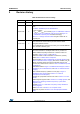
Table 95. Document revision history (continued)
Date Revision Changes