
Datasheet


DocID15818 Rev 11 95/178
STM32F20xxx Electrical characteristics
177
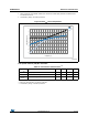
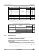
6.3.11 PLL spread spectrum clock generation (SSCG) characteristics
The spread spectrum clock generation (SSCG) feature allows to reduce electromagnetic
interferences (see Table 42: EMI characteristics). It is available only on the main PLL.
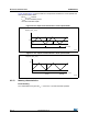
Equation 1
The frequency modulation period (MODEPER) is given by the equation below:
f
PLL_IN
and f
Mod
must be expressed in Hz.
As an example:
If f
PLL_IN
= 1 MHz and f
MOD
= 1 kHz, the modulation depth (MODEPER) is given by equation
1:
Equation 2
Equation 2 allows to calculate the increment step (INCSTEP):
f
VCO_OUT
must be expressed in MHz.
With a modulation depth (md) = ±2 % (4 % peak to peak), and PLLN = 240 (in MHz):
An amplitude quantization error may be generated because the linear modulation profile is
obtained by taking the quantized values (rounded to the nearest integer) of MODPER and
INCSTEP. As a result, the achieved modulation depth is quantized. The percentage
quantized modulation depth is given by the following formula:
As a result:
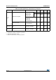
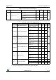
Table 36. SSCG parameters constraint
Symbol Parameter Min Typ Max
(1)
Unit
f
Mod
Modulation frequency - - 10 KHz
md Peak modulation depth 0.25 - 2 %
MODEPER * INCSTEP - - 2
15
−1-
1. Guaranteed by design, not tested in production.
MODEPER round f
PLL_IN
4f
Mod
×()⁄[]=
MODEPER round 10
6
410
3
×()⁄[]250==
INCSTEP round 2
15
1–()md PLLN××()100 5× MODEPER×()⁄[]=
INCSTEP round 2
15
1–()2 240××()100 5× 250×()⁄[]126md(quantitazed)%==
md
quantized
% MODEPER INCSTEP× 100× 5×()2
15
1–()PLLN×()⁄=
md
quantized
% 250 126× 100× 5×()2
15
1–()240×()⁄ 2.0002%(peak)==