
Datasheet


DocID15818 Rev 11 105/178
STM32F20xxx Electrical characteristics
177
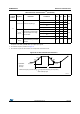
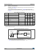
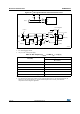
Figure 38. I/O AC characteristics definition
11
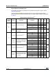
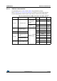
f
max(IO)out
Maximum frequency
(2)
C
L
= 30 pF, V
DD >
2.70 V - - 100
(3)
MHz
C
L
= 30 pF, V
DD >
1.8 V - - 50
(3)
C
L
= 10 pF, V
DD >
2.70 V - - 180
(3)
C
L
= 10 pF, V
DD >
1.8 V - - 100
(3)
t
f(IO)out
/
t
r(IO)out
Output high to low level fall
time and output low to high
level rise time
C
L
= 30 pF, V
DD >
2.70 V - - 4
ns
C
L
= 30 pF, V
DD >
1.8 V - - 6
C
L
= 10 pF, V
DD >
2.70 V - - 2.5
C
L
= 10 pF, V
DD >
1.8 V - - 4
-t
EXTIpw
Pulse width of external
signals detected by the EXTI
controller
10 - - ns
1. The I/O speed is configured using the OSPEEDRy[1:0] bits. Refer to the STM32F20/21xxx reference manual for a
description of the GPIOx_SPEEDR GPIO port output speed register.
2. The maximum frequency is defined in Figure 38.
3. For maximum frequencies above 50 MHz, the compensation cell should be used.
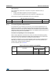
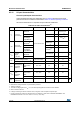
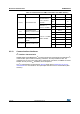
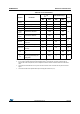
Table 48. I/O AC characteristics
(1)
(continued)
OSPEEDRy
[1:0] bit
value
(1)
Symbol Parameter Conditions Min Typ Max Unit
ai14131c
10%
90%
50%
t
r(IO)out
OUTPUT
EXTERNAL
ON 50pF
Maximum frequency is achieved if (t
r
+ t
f
) ≤ 2/3)T and if the duty cycle is (45-55%)
10%
50%
90%
when loaded by 50pF
T
t
f(IO)out