
Datasheet


Electrical characteristics STM32F103xF, STM32F103xG
96/120 Doc ID 16554 Rev 3
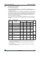
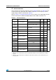
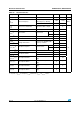
Table 57. I
2
S characteristics
Symbol Parameter Conditions Min Max Unit
DuCy(SCK) I2S slave input clock duty cycle Slave mode 30 70 %
f
CK
1/t
c(CK)
I
2
S clock frequency
Master mode (data: 16 bits,
Audio frequency = 48 kHz)
1.522 1.525
MHz
Slave mode 0 6.5
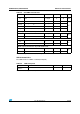
t
r(CK)
t
f(CK)
I
2
S clock rise and fall time Capacitive load C
L
= 50 pF - 8
ns
t
v(WS)
(1)
WS valid time Master mode 3 -
t
h(WS)
(1)
WS hold time Master mode
I2S2 2 -
I2S3 0 -
t
su(WS)
(1)
WS setup time Slave mode 4 -
t
h(WS)
(1)
WS hold time Slave mode 0 -
t
w(CKH)
(1)
CK high and low time
Master f
PCLK
= 16 MHz, audio
frequency = 48 kHz
312.5 -
t
w(CKL)
(1)
345 -
t
su(SD_MR)
(1)
Data input setup time Master receiver
I2S2 2 -
I2S3 6.5 -
t
su(SD_SR)
(1)
Data input setup time Slave receiver 1.5 -
t
h(SD_MR)
(1)(2)
Data input hold time
Master receiver 0 -
t
h(SD_SR)
(1)(2)
Slave receiver 0.5 -
t
v(SD_ST)
(1)(2)
Data output valid time
Slave transmitter (after enable
edge)
- 18
t
h(SD_ST)
(1)
Data output hold time
Slave transmitter (after enable
edge)
11 -
t
v(SD_MT)
(1)(2)
Data output valid time
Master transmitter (after enable
edge)
- 3
t
h(SD_MT)
(1)
Data output hold time
Master transmitter (after enable
edge)
0-
1. Based on design simulation and/or characterization results, not tested in production.
2. Depends on f
PCLK
. For example, if f
PCLK
=8 MHz, then T
PCLK
= 1/f
PLCLK
=125 ns.