
Datasheet


Electrical characteristics STM32F103xF, STM32F103xG
92/120 Doc ID 16554 Rev 3
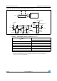
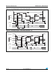
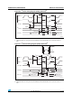
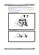
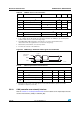
Figure 46. I
2
C bus AC waveforms and measurement circuit
1.
Measurement points are done at CMOS levels: 0.3V
DD
and 0.7V
DD
.
ai14149c
START
SD A
100
4.7k
I
2
C bus
4.7k
100
V
DD
V
DD
STM32F103xx
SDA
SCL
t
f(SDA)
t
r(SDA)
SCL
t
h(STA)
t
w(SCLH)
t
w(SCLL)
t
su(SDA)
t
r(SCL)
t
f(SCL)
t
h(SDA)
S TART REPEATED
START
t
su(STA)
t
su(STO)
S TOP
t
w(STO:STA)
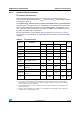
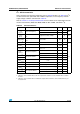
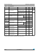
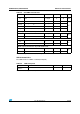
Table 55. SCL frequency (f
PCLK1
= 36 MHz.,V
DD
= 3.3 V)
(1)(2)
1. R
P
= External pull-up resistance, f
SCL
= I
2
C speed.
2. For speeds around 200 kHz, the tolerance on the achieved speed is of ±5%. For other speed ranges, the
tolerance on the achieved speed ±2%. These variations depend on the accuracy of the external
components used to design the application.
f
SCL
(kHz)
I2C_CCR value
R
P
= 4.7 kΩ
400 0x801E
300 0x8028
200 0x803C
100 0x00B4
50 0x0168
20 0x0384