
Datasheet


STM32F103xF, STM32F103xG Electrical characteristics
Doc ID 16554 Rev 3 73/120
PC Card/CompactFlash controller waveforms and timings
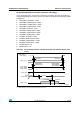
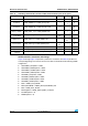
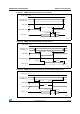
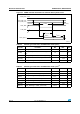
Figure 30 through Figure 35 represent synchronous waveforms and Ta ble 42 provides the
corresponding timings. The results shown in this table are obtained with the following FSMC
configuration:
● COM.FSMC_SetupTime = 0x04;
● COM.FSMC_WaitSetupTime = 0x07;
● COM.FSMC_HoldSetupTime = 0x04;
● COM.FSMC_HiZSetupTime = 0x00;
● ATT.FSMC_SetupTime = 0x04;
● ATT.FSMC_WaitSetupTime = 0x07;
● ATT.FSMC_HoldSetupTime = 0x04;
● ATT.FSMC_HiZSetupTime = 0x00;
● IO.FSMC_SetupTime = 0x04;
● IO.FSMC_WaitSetupTime = 0x07;
● IO.FSMC_HoldSetupTime = 0x04;
● IO.FSMC_HiZSetupTime = 0x00;
● TCLRSetupTime = 0;
● TARSetupTime = 0;
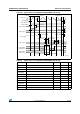
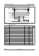
Figure 30. PC Card/CompactFlash controller waveforms for common memory read
access
1. FSMC_NCE4_2 remains high (inactive during 8-bit access.
FSMC_NWE
t
w(NOE)
FSMC_N
OE
FSMC_D[15:0]
FSMC_A[10:0]
FSMC_NCE4_2
(1)
FSMC_NCE4_1
FSMC_NREG
FSMC_NIOWR
FSMC_NIORD
t
d(NCE4_1-NOE)
t
su(D-NOE)
t
h(NOE-D)
t
v(NCEx-A)
t
d(NREG-NCEx)
t
d(NIORD-NCEx)
t
h(NCEx-AI)
t
h(NCEx-NREG)
t
h(NCEx-NIORD)
t
h(NCEx-
NIOWR
)
ai14895b