
Datasheet


STM32F103xF, STM32F103xG Electrical characteristics
Doc ID 16554 Rev 3 61/120
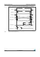
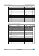
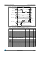
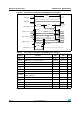
5.3.10 FSMC characteristics
Asynchronous waveforms and timings
Figure 22 through Figure 25 represent asynchronous waveforms and Table 31 through
Table 35 provide the corresponding timings. The results shown in these tables are obtained
with the following FSMC configuration:
● AddressSetupTime = 0
● AddressHoldTime = 1
● DataSetupTime = 1
Note: On all tables, the t
HCLK
is the HCLK clock period.
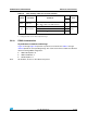
Table 30. Flash memory endurance and data retention
Symbol Parameter Conditions
Value
Unit
Min
(1)
1. Based on characterization not tested in production.
N
END
Endurance
T
A
= –40 to +85 °C (6 suffix versions)
T
A
= –40 to +105 °C (7 suffix versions)
10
kcycles
t
RET
Data retention
1 kcycle
(2)
at T
A
= 85 °C
2. Cycling performed over the whole temperature range.
30
Years1 kcycle
(2)
at T
A
= 105 °C 10
10 kcycles
(2)
at T
A
= 55 °C 20