
Datasheet


Electrical characteristics STM32F103xF, STM32F103xG
42/120 Doc ID 16554 Rev 3
5.3.2 Operating conditions at power-up / power-down
The parameters given in Ta bl e 11 are derived from tests performed under the ambient
temperature condition summarized in Ta bl e 10.
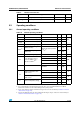
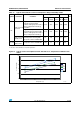
Table 11. Operating conditions at power-up / power-down
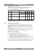
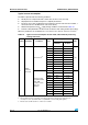
5.3.3 Embedded reset and power control block characteristics
The parameters given in Ta bl e 12 are derived from tests performed under ambient
temperature and V
DD
supply voltage conditions summarized in Table 10.
Symbol Parameter Conditions Min Max Unit
t
VDD
V
DD
rise time rate 0
∞
µs/V
V
DD
fall time rate 20
∞
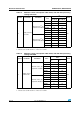
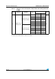
Table 12. Embedded reset and power control block characteristics
Symbol Parameter Conditions Min Typ
Max Unit
V
PVD
Programmable voltage
detector level selection
PLS[2:0]=000 (rising edge) 2.1 2.18 2.26 V
PLS[2:0]=000 (falling edge) 2 2.08 2.16 V
PLS[2:0]=001 (rising edge) 2.19 2.28 2.37 V
PLS[2:0]=001 (falling edge) 2.09 2.18 2.27 V
PLS[2:0]=010 (rising edge) 2.28 2.38 2.48 V
PLS[2:0]=010 (falling edge) 2.18 2.28 2.38 V
PLS[2:0]=011 (rising edge) 2.38 2.48 2.58 V
PLS[2:0]=011 (falling edge) 2.28 2.38 2.48 V
PLS[2:0]=100 (rising edge) 2.47 2.58 2.69 V
PLS[2:0]=100 (falling edge) 2.37 2.48 2.59 V
PLS[2:0]=101 (rising edge) 2.57 2.68 2.79 V
PLS[2:0]=101 (falling edge) 2.47 2.58 2.69 V
PLS[2:0]=110 (rising edge) 2.66 2.78 2.9 V
PLS[2:0]=110 (falling edge) 2.56 2.68 2.8 V
PLS[2:0]=111 (rising edge) 2.76 2.88 3 V
PLS[2:0]=111 (falling edge) 2.66 2.78 2.9 V
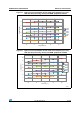
V
PVDhyst
(2)
PVD hysteresis - 100 - mV
V
POR/PDR
Power on/power down
reset threshold
Falling edge
1.8
(1)
1. The product behavior is guaranteed by design down to the minimum V
POR/PDR
value.
1.88 1.96 V
Rising edge 1.84 1.92 2.0 V
V
PDRhyst
(2)
PDR hysteresis - 40 - mV
T
RSTTEMPO
(2)
2. Guaranteed by design, not tested in production.
Reset temporization 1 2.5 4.5 mS