
Datasheet


STM32F103xC, STM32F103xD, STM32F103xE Package characteristics
Doc ID 14611 Rev 8 115/130
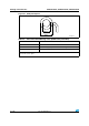
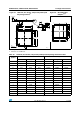
Figure 65. WLCSP, 64-ball 4.466 × 4.395 mm, 0.500 mm pitch, wafer-level chip-scale
package outline
1. Drawing is not to scale.
2. Primary datum Z and seating plane are defined by the spherical crowns of the ball.
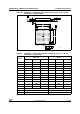
Table 68. WLCSP, 64-ball 4.466 × 4.395 mm, 0.500 mm pitch, wafer-level chip-scale
package mechanical data
Symbol
millimeters inches
(1)
1. Values in inches are converted from mm and rounded to 4 decimal digits.
Min Typ Max Min Typ Max
A 0.535 0.585 0.635 0.0211 0.0230 0.0250
A1 0.205 0.230 0.255 0.0081 0.0091 0.0100
A2 0.330 0.355 0.380 0.0130 0.0140 0.0150
b
(2)
2. Dimension is measured at the maximum ball diameter parallel to primary datum Z.
0.290 0.320 0.350 0.0114 0.0126 0.0138
e 0.500 0.0197
e1 3.500 0.1378
F 0.447 0.0176
G 0.483 0.0190
D 4.446 4.466 4.486 0.1750 0.1758 0.1766
E 4.375 4.395 4.415 0.1722 0.1730 0.1738
H 0.250 0.0098
L 0.200 0.0079
eee 0.05 0.0020
aaa 0.10 0.0039
Number of balls 64
A
B
C
D
E
F
G
H
12345678
Detail A
Side view
Ball side
Wafer back side
Marking area
A1 ball corner
A
A2
A1 ball corner
Notch
Ball
A1
b
Seating plane (see note 2)
Detail A rotated 90 ˚ CR_ME
e
e
e1
e1
F
G
D
E
aaa
eee
H
L
L