
Datasheet

Package characteristics STM32F103x8, STM32F103xB
82/105 DocID13587 Rev 16
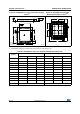
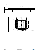
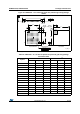
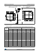
1. Drawing is not to scale.
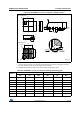
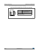
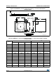
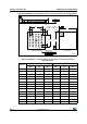
2. All leads/pads should also be soldered to the PCB to improve the lead solder joint life.
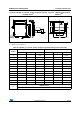
Figure 41. VFQFPN36 6 x 6 mm, 0.5 mm pitch, package
outline
(1)
Figure 42. VFQFPN36 recommended
footprint (dimensions in mm)
(1)(2)
Seating plane
ddd C
C
A3
A1
AA2
Pin # 1 ID
R = 0.20
ZR_ME
E2
b
19
10
18
27
28
36
19
D2
E
D
e
L
0.30
6.30
0.50
1.00
4.30
4.30
4.80
4.80
4.10
4.10
1
28
9
19
ai14870b
36
27
18
10
0.75
Table 51. VFQFPN36 6 x 6 mm, 0.5 mm pitch, package mechanical data
Symbol
millimeters inches
(1)
Min Typ Max Min Typ Max
A 0.800 0.900 1.000 0.0315 0.0354 0.0394
A1 - 0.020 0.050 - 0.0008 0.0020
A2 - 0.650 1.000 - 0.0256 0.0394
A3 - 0.250 - - 0.0098 -
b 0.180 0.230 0.300 0.0071 0.0091 0.0118
D 5.875 6.000 6.125 0.2313 0.2362 0.2411
D2 1.750 3.700 4.250 0.0689 0.1457 0.1673
E 5.875 6.000 6.125 0.2313 0.2362 0.2411
E2 1.750 3.700 4.250 0.0689 0.1457 0.1673
e 0.450 0.500 0.550 0.0177 0.0197 0.0217
L 0.350 0.550 0.750 0.0138 0.0217 0.0295
ddd 0.080 0.0031
1. Values in inches are converted from mm and rounded to 4 decimal digits.