
Datasheet

DocID13587 Rev 16 71/105
STM32F103x8, STM32F103xB Electrical characteristics
104
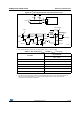
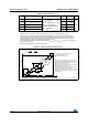
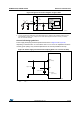
Figure 32. I
2
C bus AC waveforms and measurement circuit
1.
Measurement points are done at CMOS levels: 0.3V
DD
and 0.7V
DD
.
2. Rs = Series protection resistors, Rp = Pull-up resistors, V
DD_I2C
= I2C bus supply.
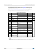
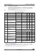
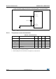
Table 41. SCL frequency (f
PCLK1
= 36 MHz.,V
DD_I2C
= 3.3 V)
(1)(2)
1. R
P
= External pull-up resistance, f
SCL
= I
2
C speed,
2. For speeds around 200 kHz, the tolerance on the achieved speed is of 5%. For other speed ranges, the
tolerance on the achieved speed 2%. These variations depend on the accuracy of the external
components used to design the application.
f
SCL
(kHz)
I2C_CCR value
R
P
= 4.7 k
400 0x801E
300 0x8028
200 0x803C
100 0x00B4
50 0x0168
20 0x0384
ai14133e
Start
SD A
I²C bus
V
DD_I2C
V
DD_I2C
STM32F10x
SDA
SCL
t
f(SDA)
t
r(SDA)
SCL
t
h(STA)
t
w(SCLH)
t
w(SCLL)
t
su(SDA)
t
r(SCL)
t
f(SCL)
t
h(SDA)
Start repeated
Start
t
su(STA)
t
su(STO)
Stop
t
su(STO:STA)
Rp
Rp
Rs
Rs