
Datasheet


Electrical characteristics STM32F103xC, STM32F103xD, STM32F103xE
60/130 Doc ID 14611 Rev 8
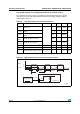
Figure 23. Typical application with a 32.768 kHz crystal
5.3.7 Internal clock source characteristics
The parameters given in Tabl e 2 5 are derived from tests performed under ambient
temperature and V
DD
supply voltage conditions summarized in Tab l e 1 0 .
High-speed internal (HSI) RC oscillator
Low-speed internal (LSI) RC oscillator
ai14146
OSC32_OU T
OSC32_IN
f
LSE
C
L1
R
F
STM32F103xx
32.768 kHz
resonator
C
L2
Resonator with
integrated capacitors
Bias
controlled
gain
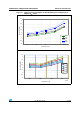
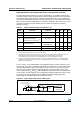
Table 25. HSI oscillator characteristics
(1)
1. V
DD
= 3.3 V, T
A
= –40 to 105 °C unless otherwise specified.
Symbol Parameter Conditions Min Typ Max Unit
f
HSI
Frequency 8 MHz
DuCy
(HSI)
Duty cycle 45 55 %
ACC
HSI
Accuracy of the HSI
oscillator
User-trimmed with the RCC_CR
register
(2)
2. Refer to application note AN2868 “STM32F10xxx internal RC oscillator (HSI) calibration” available from
the ST website www.st.com.
1
(3)
3. Guaranteed by design, not tested in production.
%
Factory-
calibrated
(4)
4. Based on characterization, not tested in production.
T
A
= –40 to 105 °C –2 2.5 %
T
A
= –10 to 85 °C –1.5 2.2 %
T
A
= 0 to 70 °C –1.3 2 %
T
A
= 25 °C –1.1 1.8 %
t
su(HSI)
(4)
HSI oscillator
startup time
12µs
I
DD(HSI)
(4)
HSI oscillator power
consumption
80 100 µA
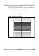
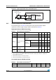
Table 26. LSI oscillator characteristics
(1)
Symbol Parameter Min Typ Max Unit
f
LSI
(2)
Frequency 30 40 60 kHz