
Datasheet

Electrical characteristics STM32F103xC, STM32F103xD, STM32F103xE
48/130 Doc ID 14611 Rev 8
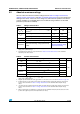
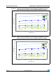
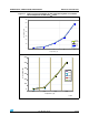
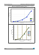
Figure 16. Typical current consumption on V
BAT
with RTC on vs. temperature at different V
BAT
values
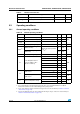
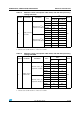
Table 17. Typical and maximum current consumptions in Stop and Standby modes
Symbol Parameter Conditions
Typ
(1)
Max
Unit
V
DD
/V
BAT
= 2.0 V
V
DD
/V
BAT
= 2.4 V
V
DD
/V
BAT
= 3.3 V
T
A
=
85 °C
T
A
=
105 °C
I
DD
Supply current in
Stop mode
Regulator in run mode, low-speed
and high-speed internal RC
oscillators and high-speed oscillator
OFF (no independent watchdog)
34.5 35 379 1130
µA
Regulator in low-power mode, low-
speed and high-speed internal RC
oscillators and high-speed oscillator
OFF (no independent watchdog)
24.5 25 365 1110
Supply current in
Standby mode
Low-speed internal RC oscillator
and independent watchdog ON
33.8--
Low-speed internal RC oscillator
ON, independent watchdog OFF
2.8 3.6 - -
Low-speed internal RC oscillator
and independent watchdog OFF,
low-speed oscillator and RTC OFF
1.9 2.1 5
(2)
6.5
(2)
I
DD_VBAT
Backup domain
supply current
Low-speed oscillator and RTC ON 1.05 1.1 1.4 2
(2)
2.3
(2)
1. Typical values are measured at T
A
= 25 °C.
2. Based on characterization, not tested in production.
0
0.5
1
1.5
2
2.5
–45 25 85105
Temperature (°C)
Consumption (µA)
1.8 V
2 V
2.4 V
3.3 V
3.6 V
ai17337