
Datasheet
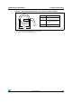
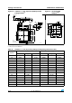

STM32F103x4, STM32F103x6 Package characteristics
Doc ID 15060 Rev 6 83/90
6.2 Thermal characteristics
The maximum chip junction temperature (T
J
max) must never exceed the values given in
Table 9: General operating conditions on page 32.
The maximum chip-junction temperature, T
J
max, in degrees Celsius, may be calculated
using the following equation:
T
J
max = T
A
max + (P
D
max × Θ
JA
)
Where:
● T
A
max is the maximum ambient temperature in ° C,
● Θ
JA
is the package junction-to-ambient thermal resistance, in ° C/W,
● P
D
max is the sum of P
INT
max and P
I/O
max (P
D
max = P
INT
max + P
I/O
max),
● P
INT
max is the product of I
DD
and
V
DD
, expressed in Watts. This is the maximum chip
internal power.
P
I/O
max represents the maximum power dissipation on output pins where:
P
I/O
max = Σ (V
OL
× I
OL
) + Σ((V
DD
– V
OH
) × I
OH
),
taking into account the actual V
OL
/ I
OL
and V
OH
/ I
OH
of the I/Os at low and high level in the
application.
6.2.1 Reference document
JESD51-2 Integrated Circuits Thermal Test Method Environment Conditions - Natural
Convection (Still Air). Available from www.jedec.org.
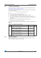
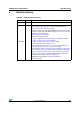
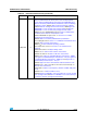
Table 56. Package thermal characteristics
Symbol Parameter Value Unit
Θ
JA
Thermal resistance junction-ambient
TFBGA64 - 5 × 5 mm / 0.5 mm pitch
65
°C/W
Thermal resistance junction-ambient
LQFP64 - 10 × 10 mm / 0.5 mm pitch
45
Thermal resistance junction-ambient
LQFP48 - 7 × 7 mm / 0.5 mm pitch
55
Thermal resistance junction-ambient
UFQFPN 48 -7 × 7 mm / 0.5 mm pitch
32
Thermal resistance junction-ambient
VFQFPN 36 - 6 × 6 mm / 0.5 mm pitch
18