
Datasheet


STM32F103x4, STM32F103x6 Electrical characteristics
Doc ID 15060 Rev 6 65/90
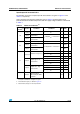
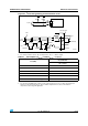
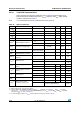
Figure 29. I
2
C bus AC waveforms and measurement circuit
1.
Measurement points are done at CMOS levels: 0.3V
DD
and 0.7V
DD
.
2. Rs = Series protection resistors, Rp = Pull-up resistors, V
DD_I2C
= I2C bus supply.
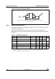
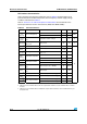
Table 41. SCL frequency (f
PCLK1
= 36 MHz.,V
DD_I2C
= 3.3 V)
(1)(2)
1. R
P
= External pull-up resistance, f
SCL
= I
2
C speed,
2. For speeds around 200 kHz, the tolerance on the achieved speed is of
±5%. For other speed ranges, the
tolerance on the achieved speed
±2%. These variations depend on the accuracy of the external
components used to design the application.
f
SCL
(kHz)
I2C_CCR value
R
P
= 4.7 kΩ
400 0x801E
300 0x8028
200 0x803C
100 0x00B4
50 0x0168
20 0x0384
AIE
3TART
3$ !
)£#BUS
6
$$?)#
6
$$?)#
34-&X
3$!
3#,
T
F3$!
T
R3$!
3#,
T
H34!
T
W3#,(
T
W3#,,
T
SU3$!
T
R3#,
T
F3#,
T
H3$!
3TARTREPEATED
3TART
T
SU34!
T
SU34/
3TOP
T
SU34/34!
Rp
Rp
Rs
Rs