
Datasheet

STM32F103x4, STM32F103x6 Electrical characteristics
Doc ID 15060 Rev 6 53/90
Designing hardened software to avoid noise problems
EMC characterization and optimization are performed at component level with a typical
application environment and simplified MCU software. It should be noted that good EMC
performance is highly dependent on the user application and the software in particular.
Therefore it is recommended that the user applies EMC software optimization and
prequalification tests in relation with the EMC level requested for his application.
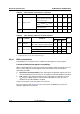
Software recommendations
The software flowchart must include the management of runaway conditions such as:
● Corrupted program counter
● Unexpected reset
● Critical Data corruption (control registers...)
Prequalification trials
Most of the common failures (unexpected reset and program counter corruption) can be
reproduced by manually forcing a low state on the NRST pin or the Oscillator pins for 1
second.
To complete these trials, ESD stress can be applied directly on the device, over the range of
specification values. When unexpected behavior is detected, the software can be hardened
to prevent unrecoverable errors occurring (see application note AN1015).
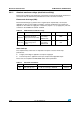
Electromagnetic Interference (EMI)
The electromagnetic field emitted by the device are monitored while a simple application is
executed (toggling 2 LEDs through the I/O ports). This emission test is compliant with
IEC 61967-2 standard which specifies the test board and the pin loading.
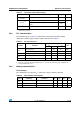
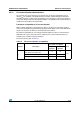
Table 30. EMS characteristics
Symbol Parameter Conditions
Level/
Class
V
FESD
Voltage limits to be applied on any I/O pin to
induce a functional disturbance
V
DD
= 3.3 V, T
A
= +25 °C,
f
HCLK
= 72 MHz
conforms to IEC 61000-4-2
2B
V
EFTB
Fast transient voltage burst limits to be
applied through 100 pF on V
DD
and V
SS
pins to induce a functional disturbance
V
DD
= 3.3 V, T
A
= +25 °C,
f
HCLK
= 72 MHz
conforms to IEC 61000-4-4
4A
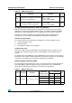
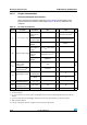
Table 31. EMI characteristics
Symbol Parameter Conditions
Monitored
frequency band
Max vs. [f
HSE
/f
HCLK
]
Unit
8/48 MHz 8/72 MHz
S
EMI
Peak level V
DD
= 3.3 V, T
A
= 25 °C
0.1 to 30 MHz 12 12
dBµV30 to 130 MHz 22 19
130 MHz to 1GHz 23 29
SAE EMI Level 4 4 -