
Datasheet

STM32F103x4, STM32F103x6 Electrical characteristics
Doc ID 15060 Rev 6 39/90
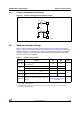
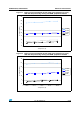
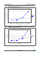
Figure 15. Typical current consumption on V
BAT
with RTC on versus temperature at different
V
BAT
values
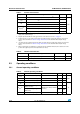
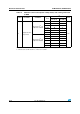
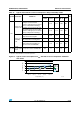
Table 16. Typical and maximum current consumptions in Stop and Standby modes
Symbol Parameter Conditions
Typ
(1)
Max
Unit
V
DD
/V
BAT
= 2.0 V
V
DD
/V
BAT
= 2.4 V
V
DD
/V
BAT
= 3.3 V
T
A
=
85 °C
T
A
=
105 °C
I
DD
Supply current
in Stop mode
Regulator in Run mode, low-speed
and high-speed internal RC
oscillators and high-speed oscillator
OFF (no independent watchdog)
- 21.3 21.7 160 200
µA
Regulator in Low Power mode, low-
speed and high-speed internal RC
oscillators and high-speed oscillator
OFF (no independent watchdog)
- 11.3 11.7 145 185
Supply current
in Standby
mode
Low-speed internal RC oscillator and
independent watchdog ON
-2.753.4--
Low-speed internal RC oscillator
ON, independent watchdog OFF
-2.553.2--
Low-speed internal RC oscillator and
independent watchdog OFF, low-
speed oscillator and RTC OFF
- 1.55 1.9 3.2 4.5
I
DD_VBAT
Backup
domain supply
current
Low-speed oscillator and RTC ON 0.9 1.1 1.4 1.9
(2)
2.2
1. Typical values are measured at T
A
= 25 °C.
2. Based on characterization, not tested in production.
0
0.5
1
1.5
2
2.5
–40 °C 25 °C 70 °C 85 °C 105 °C
Temperature (°C)
Consumption ( µA )
2 V
2.4 V
3 V
3.6 V
ai17351