
Datasheet


Revision history STM32F102x8, STM32F102xB
78/80 DocID15056 Rev 5
27-Sep-2012 4
Figure 2: Clock tree: added FLITFCLK and Note 3., and modified Note 1..
Updated Note 2. in Table 41: I2C characteristics.
Updated Figure 25: Recommended NRST pin protection.
Changed t
w(SCKH)
to
tw(SCLH
), t
w(SCKL)
to t
w(SCLL)
, t
r(SCK)
to t
r(SCL)
, t
f(SCK
)
to t
f(SCL)
, and t
su(STA:STO)
to t
w(STO:STA)
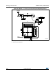
in Figure 26: I2C bus AC
waveforms and measurement circuit(1).
Changed note for I
lkg
and R
PU
and updated Note 1.content in Table 36:
I/O static characteristics. Updated text related to CMOS and TTL
compliance and added Figure 20, Figure 21, Figure 22, and Figure 23.
Updated Section : Output driving current.
In Table 43: SPI characteristics, removed note 1 related to SPI1
remapped characteristics.
Added DuCy
(HSI)
in Table 24: HSI oscillator characteristics.
Table 23: LSE oscillator characteristics (fLSE = 32.768 kHz): removed
note 2 related to oscillator selection, updated Note 2., and t
SU(LSE
)
specified for various ambient temperature values.
Updated Note 2. and Note 3. below Figure 35: Recommended footprint
(dimensions in mm)
(1)(2)(3)
.
Table 37: Output voltage characteristics: updated V
OL
and V
OH
conditions for TTL and CMOS outputs and added Note 2..
Replaced “TBD” by “-” for “max” specification of “Supply current in
Standby mode” in Table 16: Typical and maximum current consumptions
in Stop and Standby modes.
Removed “except for analog inputs” from paragraph “GPIOS (general-
purpose inputs/outputs) in
Chapter 2.3: Overview.
Updated t
w(HSE)
min value in Table 20: High-speed external user clock
characteristics.
Added Note 2. in Table 5: Voltage characteristics.
Updated Note 3., Note 4. and Note 5. in Table 6: Current characteristics.
Updated Note 1. in Table 38: I/O AC characteristics.
Added Chapter 5.3.12: I/O current injection characteristics.
Updated Note 2. in Table 41: I2C characteristics.
Updated “Output driving current” paragraph in Chapter 5.3.13: I/O port
characteristics.
Removed Note 4 and updated Note 3. in Table 41: I2C characteristics.
Updated Figure 29: SPI timing diagram - master mode(1) (SCK Output
instead of Input).
Replaced every occurrence of USBDP or USBDM by USB_DP or
USB_DM, respectively.
Table 54. Document revision history (continued)
Date Revision Changes