
Datasheet


DocID15056 Rev 5 45/80
STM32F102x8, STM32F102xB Electrical characteristics
79
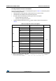
Figure 18. Typical application with an 8 MHz crystal
1. R
EXT
value depends on the crystal characteristics.
Low-speed external clock generated from a crystal/ceramic resonator
The low-speed external (LSE) clock can be supplied with a 32.768 kHz crystal/ceramic
resonator oscillator. All the information given in this paragraph are based on
characterization results obtained with typical external components specified in Table 23. In
the application, the resonator and the load capacitors have to be placed as close as
possible to the oscillator pins in order to minimize output distortion and startup stabilization
time. Refer to the crystal resonator manufacturer for more details on the resonator
characteristics (frequency, package, accuracy).
ai14977b
OSC_OU T
OSC_IN
f
HSE
C
L1
R
F
STM32F102xx
8 MHz
resonator
Bias
controlled
gain
R
EXT
(1)
C
L2
Resonator with
integrated capacitors
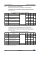
Table 22. LSE oscillator characteristics (f
LSE
= 32.768 kHz)
Symbol Parameter Conditions Min Typ Max Unit
R
F
Feedback resistor 5 MΩ
C
(1)
Recommended load capacitance
versus equivalent serial
resistance of the crystal (R
S
)
R
S
= 30 kΩ 15 pF
I
2
LSE driving current
V
DD
= 3.3 V
V
IN
= V
SS
1.4 µA
g
m
Oscillator transconductance 5 µA/V
t
SU(LSE)
(2)
Startup time V
DD
is stabilized
T
A
= 50 °C 1.5
s
T
A
= 25 °C 2.5
T
A
= 10 °C 4.0
T
A
= 0 °C 6.0
T
A
= −10°C 10.0
T
A
= −20°C 17.0
T
A
= −30°C 32.0
T
A
= −40°C 60.0
1. Refer to the note and caution paragraphs below the table, and to the application note AN2867 “Oscillator design guide for
ST microcontrollers”.
2. t
SU(LSE)
is the startup time measured from the moment it is enabled by software to a stabilized 32.768 kHz oscillation is
reached. This value is measured for a standard crystal and can vary significantly with the crystal manufacturer, PCB layout
and humidity.