
Datasheet


Electrical characteristics STM32F101xF, STM32F101xG
74/108 Doc ID 17143 Rev 2
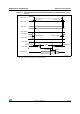
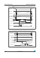
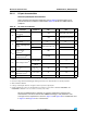
NAND controller waveforms and timings
Figure 35 through Figure 38 represent synchronous waveforms and Tabl e 4 0 provides the
corresponding timings. The results shown in this table are obtained with the following FSMC
configuration:
● COM.FSMC_SetupTime = 0x01;
● COM.FSMC_WaitSetupTime = 0x03;
● COM.FSMC_HoldSetupTime = 0x02;
● COM.FSMC_HiZSetupTime = 0x01;
● ATT.FSMC_SetupTime = 0x01;
● ATT.FSMC_WaitSetupTime = 0x03;
● ATT.FSMC_HoldSetupTime = 0x02;
● ATT.FSMC_HiZSetupTime = 0x01;
● Bank = FSMC_Bank_NAND;
● MemoryDataWidth = FSMC_MemoryDataWidth_16b;
● ECC = FSMC_ECC_Enable;
● ECCPageSize = FSMC_ECCPageSize_512Bytes;
● TCLRSetupTime = 0;
● TARSetupTime = 0;
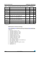
t
d(D-NWE)
FSMC_D[15:0] valid before FSMC_NWE high 13T
HCLK
ns
t
w(NIOWR)
FSMC_NIOWR low width 8T
HCLK
+ 3 ns
t
v(NIOWR-D)
FSMC_NIOWR low to FSMC_D[15:0] valid 5T
HCLK
+1 ns
t
h(NIOWR-D)
FSMC_NIOWR high to FSMC_D[15:0] invalid 11T
HCLK
ns
t
d(NCE4_1-NIOWR)
FSMC_NCE4_1 low to FSMC_NIOWR valid 5T
HCLK
+3ns ns
t
h(NCEx-NIOWR)
t
h(NCE4_1-NIOWR)
FSMC_NCEx high to FSMC_NIOWR invalid
FSMC_NCE4_1 high to FSMC_NIOWR invalid
5T
HCLK
– 5 ns
t
d(NIORD-NCEx)
t
d(NIORD-NCE4_1)
FSMC_NCEx low to FSMC_NIORD valid
FSMC_NCE4_1 low to FSMC_NIORD valid
5T
HCLK
+ 2.5 ns
t
h(NCEx-NIORD)
t
h(NCE4_1-NIORD)
FSMC_NCEx high to FSMC_NIORD invalid
FSMC_NCE4_1 high to FSMC_NIORD invalid
5T
HCLK
– 5 ns
t
su(D-NIORD)
FSMC_D[15:0] valid before FSMC_NIORD high 4.5 ns
t
d(NIORD-D)
FSMC_D[15:0] valid after FSMC_NIORD high 9 ns
t
w(NIORD)
FSMC_NIORD low width 8T
HCLK
+ 2 ns
1. C
L
= 15 pF.
2. Preliminary values.
Table 39. Switching characteristics for PC Card/CF read and write cycles
(1)(2)
(continued)
Symbol Parameter Min Max Unit