
Datasheet


STM32F101xF, STM32F101xG Electrical characteristics
Doc ID 17143 Rev 2 69/108
PC Card/CompactFlash controller waveforms and timings
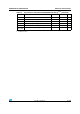
Figure 29 through Figure 34 represent synchronous waveforms and Tabl e 3 9 provides the
corresponding timings. The results shown in this table are obtained with the following FSMC
configuration:
● COM.FSMC_SetupTime = 0x04;
● COM.FSMC_WaitSetupTime = 0x07;
● COM.FSMC_HoldSetupTime = 0x04;
● COM.FSMC_HiZSetupTime = 0x00;
● ATT.FSMC_SetupTime = 0x04;
● ATT.FSMC_WaitSetupTime = 0x07;
● ATT.FSMC_HoldSetupTime = 0x04;
● ATT.FSMC_HiZSetupTime = 0x00;
● IO.FSMC_SetupTime = 0x04;
● IO.FSMC_WaitSetupTime = 0x07;
● IO.FSMC_HoldSetupTime = 0x04;
● IO.FSMC_HiZSetupTime = 0x00;
● TCLRSetupTime = 0;
● TARSetupTime = 0;
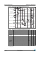
Figure 29. PC Card/CompactFlash controller waveforms for common memory read
access
1. FSMC_NCE4_2 remains high (inactive during 8-bit access.
FSMC_NWE
t
w(NOE)
FSMC_N
OE
FSMC_D[15:0]
FSMC_A[10:0]
FSMC_NCE4_2
(1)
FSMC_NCE4_1
FSMC_NREG
FSMC_NIOWR
FSMC_NIORD
t
d(NCE4_1-NOE)
t
su(D-NOE)
t
h(NOE-D)
t
v(NCEx-A)
t
d(NREG-NCEx)
t
d(NIORD-NCEx)
t
h(NCEx-AI)
t
h(NCEx-NREG)
t
h(NCEx-NIORD)
t
h(NCEx-
NIOWR
)
ai14895b