
Datasheet


Electrical characteristics STM32F101xF, STM32F101xG
54/108 Doc ID 17143 Rev 2
Note: For C
L1
and C
L2
, it is recommended to use high-quality ceramic capacitors in the 5 pF to
15 pF range selected to match the requirements of the crystal or resonator. C
L1
and C
L2,
are
usually the same size. The crystal manufacturer typically specifies a load capacitance which
is the series combination of C
L1
and C
L2
.
Load capacitance C
L
has the following formula: C
L
= C
L1
x C
L2
/ (C
L1
+ C
L2
) + C
stray
where
C
stray
is the pin capacitance and board or trace PCB-related capacitance. Typically, it is
between 2 pF and 7 pF.
Caution: To avoid exceeding the maximum value of C
L1
and C
L2
(15 pF) it is strongly recommended
to use a resonator with a load capacitance C
L
7 pF. Never use a resonator with a load
capacitance of 12.5 pF.
Example: if you choose a resonator with a load capacitance of C
L
= 6 pF, and C
stray
= 2 pF,
then C
L1
= C
L2
= 8 pF.
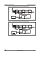
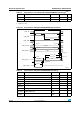
Figure 20. Typical application with a 32.768 kHz crystal
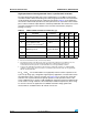
5.3.7 Internal clock source characteristics
The parameters given in Ta ble 2 5 are derived from tests performed under ambient
temperature and V
DD
supply voltage conditions summarized in Table 10 .
High-speed internal (HSI) RC oscillator
ai14129b
OSC32_OUT
OSC32_IN
f
LSE
C
L1
R
F
STM32F10xxx
32.768 KHz
resonator
Resonator with
integrated capacitors
Bias
controlled
gain
C
L2
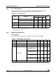
Table 25. HSI oscillator characteristics
(1)
1. V
DD
= 3.3 V, T
A
= –40 to 85 °C unless otherwise specified.
Symbol Parameter Conditions Min Typ Max Unit
f
HSI
Frequency 8 MHz
DuCy
(HSI)
Duty cycle 45 55 %
ACC
HSI
Accuracy of the HSI
oscillator
User-trimmed with the RCC_CR
register
(2)
1
(3)
%
Factory-
calibrated
(4)
T
A
= –40 to 105 °C –2 2.5 %
T
A
= –10 to 85 °C –1.5 2.2 %
T
A
= 0 to 70 °C –1.3 2 %
T
A
= 25 °C –1.1 1.8 %
t
su(HSI)
(4)
HSI oscillator startup
time
12µs
I
DD(HSI)
(4)
HSI oscillator power
consumption
80 100 µA