
Datasheet


STM32F101xF, STM32F101xG Electrical characteristics
Doc ID 17143 Rev 2 35/108
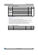
5.1.5 Pin input voltage
The input voltage measurement on a pin of the device is described in Figure 8.
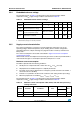
5.1.6 Power supply scheme
Figure 9. Power supply scheme
Caution: In Figure 9, the 4.7 µF capacitor must be connected to V
DD3
.
Figure 7. Pin loading conditions Figure 8. Pin input voltage
ai14123
C=50pF
STM32F101 PIN
ai14124
STM32F101 PIN
V
IN
AI
6
$$
!NALO G
2#S0,,
0OWERSWITCH
6
"!4
'0)/ S
/54
).
+ERNELLOGIC
#05
$IGITAL
-EMORIES
"ACKUPCIRCUITRY
/3#+24#
"ACKUPREGISTERS
7AKEUPLOGIC
§N&
§&
6
2EGULATOR
6
33
6
$$!
6
2%&
6
2%&
6
33!
!$#
$!#
,EVELSHIFTER
)/
,OGIC
6
$$
N&
&
6
2%&
N&
&
6
$$