
Datasheet


STM32F101xF, STM32F101xG Description
Doc ID 17143 Rev 2 19/108
2.3.17 RTC (real-time clock) and backup registers
The RTC and the backup registers are supplied through a switch that takes power either on
V
DD
supply when present or through the V
BAT
pin. The backup registers are forty-two 16-bit
registers used to store 84 bytes of user application data when V
DD
power is not present.
They are not reset by a system or power reset, and they are not reset when the device
wakes up from the Standby mode.
The real-time clock provides a set of continuously running counters which can be used with
suitable software to provide a clock calendar function, and provides an alarm interrupt and a
periodic interrupt. It is clocked by a 32.768 kHz external crystal, resonator or oscillator, the
internal low power RC oscillator or the high speed external clock divided by 128. The
internal low-speed RC has a typical frequency of 40 kHz. The RTC can be calibrated using
an external 512 Hz output to compensate for any natural quartz deviation. The RTC features
a 32-bit programmable counter for long term measurement using the Compare register to
generate an alarm. A 20-bit prescaler is used for the time base clock and is by default
configured to generate a time base of 1 second from a clock at 32.768 kHz.
2.3.18 Timers and watchdogs
The XL-density STM32F101xx access line devices include up to ten general-purpose
timers, two basic timers, two watchdog timers and a SysTick timer.
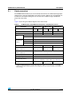
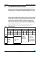
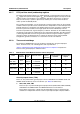
Table 4: STM32F101xF and STM32F101xG timer feature comparison compares the
features of the general-purpose and basic timers.
General-purpose timers (TIMx)
There are 10 synchronizable general-purpose timers embedded in the STM32F101xF and
STM32F101xG XL-density access line devices (see Ta ble 4 for differences).
● TIM2, TIM3, TIM4, TIM5
There are up to 4 synchronizable general-purpose timers (TIM2, TIM3, TIM4 and TIM5)
embedded in the STM32F101xF and STM32F101xG access line devices.
These timers are based on a 16-bit auto-reload up/down counter, a 16-bit prescaler
and feature 4 independent channels each for input capture/output compare, PWM or
Table 4. STM32F101xF and STM32F101xG timer feature comparison
Timer
Counter
resolution
Counter
type
Prescaler factor
DMA
request
generation
Capture/compare
channels
Complementary
outputs
TIM2, TIM3,
TIM4, TIM5
16-bit
Up, down,
up/down
Any integer between
1 and 65536
Ye s 4 N o
TIM9, TIM12 16-bit Up
Any integer between
1 and 65536
No 2 No
TIM10, TIM11,
TIM13, TIM14
16-bit Up
Any integer between
1 and 65536
No 1 No
TIM6, TIM7 16-bit Up
Any integer between
1 and 65536
Ye s 0 N o