
Datasheet


STM32F101xF, STM32F101xG Package characteristics
Doc ID 17143 Rev 2 105/108
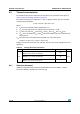
6.2.2 Evaluating the maximum junction temperature for an application
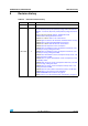
When ordering the microcontroller, the temperature range is specified in the ordering
information scheme shown in Table 65: STM32F101xF and STM32F101xG ordering
information scheme.
Each temperature range suffix corresponds to a specific guaranteed ambient temperature at
maximum dissipation and, to a specific maximum junction temperature. Here, only
temperature range 6 is available (–40 to 85 °C).
The following example shows how to calculate the temperature range needed for a given
application, making it possible to check whether the required temperature range is
compatible with the STM32F10xxx junction temperature range.
Example: High-performance application
Assuming the following application conditions:
Maximum ambient temperature T
Amax
= 82 °C (measured according to JESD51-2),
I
DDmax
= 50 mA, V
DD
= 3.5 V, maximum 20 I/Os used at the same time in output at low
level with I
OL
= 8 mA, V
OL
= 0.4 V and maximum 8 I/Os used at the same time in output
mode at low level with I
OL
= 20 mA, V
OL
= 1.3 V
P
INTmax
=
50 mA × 3.5 V= 175 mW
P
IOmax
=
20 × 8 mA × 0.4 V + 8 × 20 mA × 1.3 V = 272 mW
This gives: P
INTmax
= 175 mW and P
IOmax
= 272 mW
P
Dmax
=
175
+
272 = 447 mW
Thus: P
Dmax
= 447 mW
Using the values obtained in Table 6 5 T
Jmax
is calculated as follows:
– For LQFP64, 45 °C/W
T
Jmax
= 82 °C + (45 °C/W × 447 mW) = 82 °C + 20.1 °C = 102.1 °C
This is within the junction temperature range of the STM32F10xxx (–40 < T
J
< 105 °C).
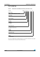
Figure 60. LQFP64 P
D
max vs. T
A
0
100
200
300
400
500
600
700
65 75 85 95 105 115
T
A
(°C)
P
D
(mW)
Suffix 6