
Datasheet


DocID13586 Rev 16 81/90
STM32F101x8, STM32F101xB Package characteristics
89
6.2.2 Evaluating the maximum junction temperature for an application
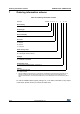
When ordering the microcontroller, the temperature range is specified in the ordering
information scheme shown in Table 53: Ordering information scheme.
Each temperature range suffix corresponds to a specific guaranteed ambient temperature at
maximum dissipation and, to a specific maximum junction temperature. Here, only
temperature range 6 is available (–40 to 85 °C).
The following example shows how to calculate the temperature range needed for a given
application, making it possible to check whether the required temperature range is
compatible with the STM32F101xx junction temperature range.
Example: high-performance application
Assuming the following application conditions:
Maximum ambient temperature T
Amax
= 82 °C (measured according to JESD51-2),
I
DDmax
= 50 mA, V
DD
= 3.5 V, maximum 20 I/Os used at the same time in output at low
level with I
OL
= 8 mA, V
OL
= 0.4 V and maximum 8 I/Os used at the same time in output
mode at low level with I
OL
= 20 mA, V
OL
= 1.3 V
P
INTmax
=
50 mA × 3.5 V= 175 mW
P
IOmax
=
20 × 8 mA × 0.4 V + 8 × 20 mA × 1.3 V = 272 mW
This gives: P
INTmax
= 175 mW and P
IOmax
= 272 mW
P
Dmax
=
175
+
272 = 447 mW
Thus: P
Dmax
= 447 mW
Using the values obtained in Table 52 T
Jmax
is calculated as follows:
– For LQFP64, 45 °C/W
T
Jmax
= 82 °C + (45 °C/W × 447 mW) = 82 °C + 20.1 °C = 102.1 °C
This is within the junction temperature range of the STM32F101xx (–40 < T
J
< 105 °C).
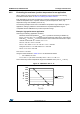
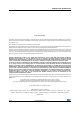
Figure 47. LQFP64 P
D
max vs. T
A
0
100
200
300
400
500
600
700
65 75 85 95 105 115
T
A
(°C)
P
D
(mW)
Suffix 6