
Datasheet

DocID13586 Rev 16 59/90
STM32F101x8, STM32F101xB Electrical characteristics
89
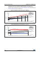
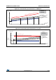
Input/output AC characteristics
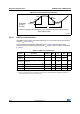
The definition and values of input/output AC characteristics are given in Figure 27 and
Table 36, respectively.
Unless otherwise specified, the parameters given in Table 36 are derived from tests
performed under the ambient temperature and V
DD
supply voltage conditions summarized
in Table 8 .
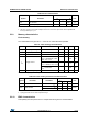
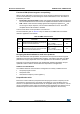
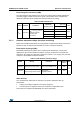
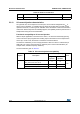
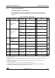
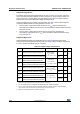
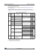
Table 36. I/O AC characteristics
(1)
1. The I/O speed is configured using the MODEx[1:0] bits. Refer to the STM32F10xxx reference manual for a
description of GPIO Port configuration register.
MODEx
[1:0] bit
value
(1)
Symbol Parameter Conditions Max Unit
10
f
max(IO)out
Maximum frequency
(2)
2. The maximum frequency is defined in Figure 27.
C
L
= 50 pF, V
DD
= 2 V to 3.6 V 2 MHz
t
f(IO)out
Output high to low level fall
time
C
L
= 50 pF, V
DD
= 2 V to 3.6 V
125
(3)
3. Guaranteed by design, not tested in production.
ns
t
r(IO)out
Output low to high level rise
time
125
(3)
01
f
max(IO)out
Maximum frequency
(2)
C
L
= 50 pF, V
DD
= 2 V to 3.6 V 10 MHz
t
f(IO)out
Output high to low level fall
time
C
L
= 50 pF, V
DD
= 2 V to 3.6 V
25
(3)
ns
t
r(IO)out
Output low to high level rise
time
25
(3)
11
F
max(IO)out
Maximum Frequency
(2)
C
L
= 30 pF, V
DD
= 2.7 V to 3.6 V 50 MHz
C
L
= 50 pF, V
DD
= 2.7 V to 3.6 V 30 MHz
C
L
= 50 pF, V
DD
= 2 V to 2.7 V 20 MHz
t
f(IO)out
Output high to low level fall
time
C
L
= 30 pF, V
DD
= 2.7 V to 3.6 V 5
(3)
ns
C
L
= 50 pF, V
DD
= 2.7 V to 3.6 V 8
(3)
C
L
= 50 pF, V
DD
= 2 V to 2.7 V 12
(3)
t
r(IO)out
Output low to high level rise
time
C
L
= 30 pF, V
DD
= 2.7 V to 3.6
V
5
(3)
C
L
= 50 pF, V
DD
= 2.7 V to 3.6 V 8
(3)
C
L
= 50 pF, V
DD
= 2 V to 2.7 V 12
(3)
-t
EXTIpw
Pulse width of external
signals detected by the
EXTI controller
10 ns