
Datasheet

Electrical characteristics STM32F101x8, STM32F101xB
48/90 DocID13586 Rev 16
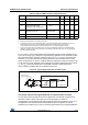
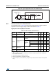
time. Refer to the crystal resonator manufacturer for more details on the resonator
characteristics (frequency, package, accuracy).
Note: For C
L1
and C
L2
it is recommended to use high-quality ceramic capacitors in the 5 pF to
15 pF range selected to match the requirements of the crystal or resonator. C
L1
and C
L2,
are
usually the same size. The crystal manufacturer typically specifies a load capacitance which
is the series combination of C
L1
and C
L2
.
Load capacitance C
L
has the following formula: C
L
= C
L1
x C
L2
/ (C
L1
+ C
L2
) + C
stray
where
C
stray
is the pin capacitance and board or trace PCB-related capacitance. Typically, it is
between 2 pF and 7 pF.
Caution: To avoid exceeding the maximum value of C
L1
and C
L2
(15 pF) it is strongly recommended
to use a resonator with a load capacitance C
L
7 pF. Never use a resonator with a load
capacitance of 12.5 pF.
Example: if you choose a resonator with a load capacitance of C
L
= 6 pF, and C
stray
= 2 pF,
then C
L1
= C
L2
= 8 pF.
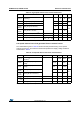
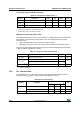
Table 22. LSE oscillator characteristics (f
LSE
= 32.768 kHz)
(1)
(2)
Symbol Parameter Conditions Min Typ Max Unit
R
F
Feedback resistor 5 M
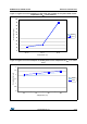
C
Recommended load capacitance
versus equivalent serial
resistance of the crystal (R
S
)
R
S
= 30 K 15 pF
I
2
LSE driving current
V
DD
= 3.3 V
V
IN
= V
SS
1.4 µA
g
m
Oscillator transconductance 5 µA/V
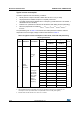
t
SU(LSE)
(3)
Startup time
V
DD
is
stabilized
T
A
= 50 °C 1.5
s
T
A
= 25 °C 2.5
T
A
= 10 °C 4
T
A
= 0 °C 6
T
A
= -10 °C 10
T
A
= -20 °C 17
T
A
= -30 °C 32
T
A
= -40 °C 60
1. Based on characterization, not tested in production.
2. Refer to the note and caution paragraphs below the table, and to the application note AN2867 “Oscillator design guide for
ST microcontrollers”.
3. t
SU(LSE)
is the startup time measured from the moment it is enabled (by software) to a stabilized 32.768 kHz oscillation is
reached. This value is measured for a standard crystal and it can vary significantly with the crystal manufacturer