
Datasheet


DocID13586 Rev 16 39/90
STM32F101x8, STM32F101xB Electrical characteristics
89
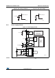
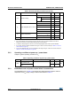
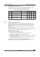
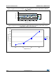
Table 14. Maximum current consumption in Sleep mode, code running from Flash
or RAM
Symbol Parameter Conditions f
HCLK
Max
(1)
1. Based on characterization, tested in production at V
DD
max and f
HCLK
max with peripherals enabled.
Unit
T
A
= 85 °C
I
DD
Supply current in
Sleep mode
External clock
(2)
all
peripherals enabled
2. External clock is 8 MHz and PLL is on when f
HCLK
> 8 MHz.
36 MHz 15.5
mA
24 MHz 11.5
16 MHz 8.5
8 MHz 5.5
External clock
(2)
, all
peripherals disabled
36 MHz 5
24 MHz 4.5
16 MHz 4
8 MHz 3
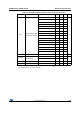
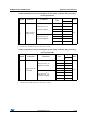
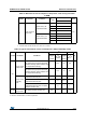
Table 15. Typical and maximum current consumptions in Stop and Standby modes
Symbol Parameter Conditions
Typ
(1)
Max
Unit
V
DD
/V
BA
T
= 2.0 V
V
DD
/ V
BAT
= 2.4 V
V
DD
/V
BA
T
= 3.3 V
T
A
=
85 °C
(2)
I
DD
Supply current
in Stop mode
Regulator in Run mode,
Low-speed and high-speed internal RC
oscillators and high-speed oscillator OFF
(no independent watchdog)
- 23.5 24 200
µA
Regulator in Low-Power mode,
Low-speed and high-speed internal RC
oscillators and high-speed oscillator OFF
(no independent watchdog)
- 13.5 14 180
Supply current
in Standby
mode
Low-speed internal RC oscillator and
independent watchdog ON
-2.63.4-
Low-speed internal RC oscillator ON,
independent watchdog OFF
-2.43.2-
Low-speed internal RC oscillator and
independent watchdog OFF, low-speed
oscillator and RTC OFF
-1.724
I
DD_VBAT
Backup domain
supply current
Low-speed oscillator and RTC ON 0.9 1.1 1.4 1.9
1. Typical values are measured at T
A
= 25 °C.
2. Based on characterization, not rested in production.