
Datasheet


Package characteristics STM32F101x4, STM32F101x6
70/79 Doc ID 15058 Rev 5
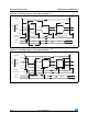
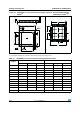
1. Drawing is not to scale.
2. All leads/pads should also be soldered to the PCB to improve the lead solder joint life.
Figure 35. VFQFPN48 7 x 7 mm, 0.5 mm pitch, package
outline
(1)
Figure 36. Recommended footprint
(dimensions in mm)
(1)(2)
Seating
Plane
C
A3
A1
A2
A
ddd C
Pin no. 1 ID
R = 0.20
Bottom View
1
48
e
E
L
L
12
13
D2
b
24
25
b
E2
36
37
e
D
V0_ME
0.50
7.30
0.75
5.80
5.80
6.20
6.20
5.60
5.60
13
1
24
37
ai15799
12
48
36
25
0.55
0.30
0.20
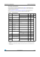
Table 47. VFQFPN48 7 x 7 mm, 0.5 mm pitch, package mechanical data
Symbol
millimeters inches
(1)
Min Typ Max Min Typ Max
A 0.800 0.900 1.000 0.0315 0.0354 0.0394
A1 0.020 0.050 0.0008 0.0020
A2 0.650 1.000 0.0256 0.0394
A3 0.250 0.0098
b 0.180 0.230 0.300 0.0071 0.0091 0.0118
D 6.850 7.000 7.150 0.2697 0.2756 0.2815
D2 2.250 4.700 5.250 0.0886 0.1850 0.2067
E 6.850 7.000 7.150 0.2697 0.2756 0.2815
E2 2.250 4.700 5.250 0.0886 0.1850 0.2067
e 0.450 0.500 0.550 0.0177 0.0197 0.0217
L 0.300 0.400 0.500 0.0118 0.0157 0.0197
ddd 0.080 0.0031
1. Values in inches are converted from mm and rounded to 4 decimal digits.