
Datasheet


STM32F101x4, STM32F101x6 Electrical characteristics
Doc ID 15058 Rev 5 59/79
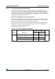
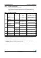
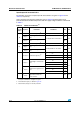
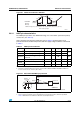
Table 39. I
2
C characteristics
Symbol Parameter
Standard mode I
2
C
(1)
1.
Guaranteed by design, not tested in production.
Fast mode I
2
C
(1)(2)
2. f
PCLK1
must be higher than 2 MHz to achieve standard mode I
2
C frequencies. It must be higher than
4 MHz to achieve fast mode I
2
C frequencies. It must be a multiple of 10 MHz to reach the 400 kHz
maximum I2C fast mode clock.
Unit
Min Max Min Max
t
w(SCLL)
SCL clock low time 4.7 1.3
µs
t
w(SCLH)
SCL clock high time 4.0 0.6
t
su(SDA)
SDA setup time 250 100
ns
t
h(SDA)
SDA data hold time 0
(3)
3.
The maximum hold time of the Start condition has only to be met if the interface does not stretch the low
period of SCL signal.
0
(4)
4.
The device must internally provide a hold time of at least 300 ns for the SDA signal in order to bridge the
undefined region of the falling edge of SCL.
900
(3)
t
r(SDA)
t
r(SCL)
SDA and SCL rise time 1000 20+0.1C
b
300
t
f(SDA)
t
f(SCL)
SDA and SCL fall time 300 300
t
h(STA)
Start condition hold time 4.0 0.6
µs
t
su(STA)
Repeated Start condition setup
time
4.7 0.6
t
su(STO)
Stop condition setup time 4.0 0.6 µs
t
w(STO:STA)
Stop to Start condition time (bus
free)
4.7 1.3 µs
C
b
Capacitive load for each bus line 400 400 pF