
Datasheet


STM32F100xC, STM32F100xD, STM32F100xE Electrical characteristics
Doc ID 15081 Rev 7 77/98
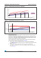
Figure 29. I
2
C bus AC waveforms and measurement circuit
1. Measurement points are done at CMOS levels: 0.3V
DD
and 0.7V
DD
.
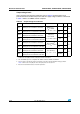
Table 49. SCL frequency (f
PCLK1
= 24 MHz, V
DD
= 3.3 V)
(1)(2)
1. R
P
= External pull-up resistance, f
SCL
= I
2
C speed,
2. For speeds around 400 kHz, the tolerance on the achieved speed is of ±2%. For other speed ranges, the
tolerance on the achieved speed ±1%. These variations depend on the accuracy of the external
components used to design the application.
f
SCL
(kHz)
(3)
3.
Guaranteed by design, not tested in production.
I2C_CCR value
R
P
= 4.7 kΩ
400 0x8011
300 0x8016
200 0x8021
100 0x0064
50 0x00C8
20 0x01F4
DLG
6WDUW
6' $
!
N!
,ð&EXV
N!
!
9
''
9
''
670)[
6'$
6&/
W
I6'$
W
U6'$
6&/
W
K67$
W
Z6&/+
W
Z6&//
W
VX6'$
W
U6&/
W
I6&/
W
K6'$
6WDUWUHSHDWHG
6WDUW
W
VX67$
W
VX672
6WRS
W
VX67267$