
Datasheet

Electrical characteristics STM32F100x4, STM32F100x6, STM32F100x8, STM32F100xB
48/88 Doc ID 16455 Rev 7
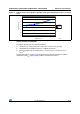
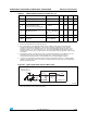
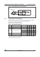
Low-speed external clock generated from a crystal/ceramic resonator
The low-speed external (LSE) clock can be supplied with a 32.768 kHz crystal/ceramic
resonator oscillator. All the information given in this paragraph are based on characterization
results obtained with typical external components specified in Tabl e 22 . In the application,
the resonator and the load capacitors have to be placed as close as possible to the oscillator
pins in order to minimize output distortion and startup stabilization time. Refer to the crystal
resonator manufacturer for more details on the resonator characteristics (frequency,
package, accuracy).
Note: For C
L1
and C
L2
it is recommended to use high-quality ceramic capacitors in the 5 pF to
15 pF range selected to match the requirements of the crystal or resonator. C
L1
and C
L2,
are
usually the same size. The crystal manufacturer typically specifies a load capacitance which
is the series combination of C
L1
and C
L2
.
Load capacitance C
L
has the following formula: C
L
= C
L1
x C
L2
/ (C
L1
+ C
L2
) + C
stray
where
C
stray
is the pin capacitance and board or trace PCB-related capacitance. Typically, it is
between 2 pF and 7 pF.
Caution: To avoid exceeding the maximum value of C
L1
and C
L2
(15 pF) it is strongly recommended
to use a resonator with a load capacitance C
L
7 pF. Never use a resonator with a load
capacitance of 12.5 pF.
Example: if you choose a resonator with a load capacitance of C
L
= 6 pF, and C
stray
= 2 pF,
then C
L1
= C
L2
= 8 pF.
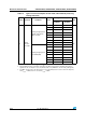
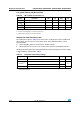
Table 22. LSE oscillator characteristics (f
LSE
= 32.768 kHz)
(1)
Symbol Parameter Conditions Min Typ Max Unit
R
F
Feedback resistor 5 M
C
L1
C
L2
(2)
Recommended load capacitance
versus equivalent serial
resistance of the crystal (R
S
)
(3)
R
S
= 30 K 15 pF
I
2
LSE driving current
V
DD
= 3.3 V
V
IN
= V
SS
1.4 µA
g
m
Oscillator transconductance 5 µA/V
t
SU(LSE)
(4)
Startup time
V
DD
is
stabilized
T
A
= 50 °C 1.5
s
T
A
= 25 °C 2.5
T
A
= 10 °C 4
T
A
= 0 °C 6
T
A
= -10 °C 10
T
A
= -20 °C 17
T
A
= -30 °C 32
T
A
= -40 °C 60
1. Based on characterization, not tested in production.
2. Refer to the note and caution paragraphs above the table.
3. The oscillator selection can be optimized in terms of supply current using an high quality resonator with small R
S
value for
example MSIV-TIN32.768 kHz. Refer to crystal manufacturer for more details
4. t
SU(LSE)
is the startup time measured from the moment it is enabled (by software) to a stabilized 32.768 kHz oscillation is
reached. This value is measured for a standard crystal and it can vary significantly with the crystal manufacturer