
Datasheet


Electrical characteristics STM32F100x4, STM32F100x6, STM32F100x8, STM32F100xB
64/88 Doc ID 16455 Rev 7
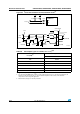
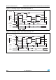
Figure 28. I
2
C bus AC waveforms and measurement circuit
(1)
1. Measurement points are done at CMOS levels: 0.3V
DD
and 0.7V
DD
.
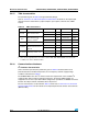
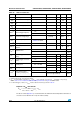
Table 40. SCL frequency (f
PCLK1
= 24 MHz, V
DD
= 3.3 V)
(1)(2)
1. R
P
= External pull-up resistance, f
SCL
= I
2
C speed,
2. For speeds around 400 kHz, the tolerance on the achieved speed is of 2%. For other speed ranges, the
tolerance on the achieved speed 1%. These variations depend on the accuracy of the external
components used to design the application.
f
SCL
(kHz)
(3)
3.
Guaranteed by design, not tested in production.
I2C_CCR value
R
P
= 4.7 k
400 0x8011
300 0x8016
200 0x8021
100 0x0064
50 0x00C8
20 0x01F4
AID
3TART
3$ !
Ω
KΩ
)£#BUS
KΩ
Ω
6
$$
6
$$
34-&X
3$!
3#,
T
F3$!
T
R3$!
3#,
T
H34!
T
W3#,(
T
W3#,,
T
SU3$!
T
R3#,
T
F3#,
T
H3$!
3TARTREPEATED
3TART
T
SU34!
T
SU34/
3TOP
T
SU34/34!