
Datasheet


STM32F100x4, STM32F100x6, STM32F100x8, STM32F100xB Electrical characteristics
Doc ID 16455 Rev 7 39/88
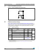
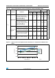
Figure 14. Typical current consumption on V
BAT
with RTC on vs. temperature at different V
BAT
values
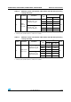
Table 15. Typical and maximum current consumptions in Stop and Standby modes
Symbol Parameter Conditions
Typ
(1)
Max
Unit
V
DD
/V
BAT
= 2.0 V
V
DD
/ V
BAT
= 2.4 V
V
DD
/V
BAT
= 3.3 V
T
A
=
85 °C
T
A
=
105 °C
I
DD
Supply current
in Stop mode
Regulator in Run mode,
Low-speed and high-speed
internal RC oscillators and high-
speed oscillator OFF (no
independent watchdog)
23.5 24 190 350
µA
Regulator in Low-Power mode,
Low-speed and high-speed
internal RC oscillators and high-
speed oscillator OFF (no
independent watchdog)
13.5 14 170 330
Supply current
in Standby
mode
Low-speed internal RC oscillator
and independent watchdog ON
2.6 3.4 - -
Low-speed internal RC oscillator
ON, independent watchdog OFF
2.4 3.2 - -
Low-speed internal RC oscillator
and independent watchdog OFF,
low-speed oscillator and RTC
OFF
1.7 2 4 5
I
DD_VBAT
Backup
domain supply
current
Low-speed oscillator and RTC
ON
0.9 1.1 1.4 1.9 2.2
1. Typical values are measured at T
A
= 25 °C.
0.00
0.50
1.00
1.50
2.00
-45°C
25°C
85°C
105°C
3.6 V
3.3 V
2.4 V
2 V
ai15792
Temperature (°C)
IDD_VBAT (µA)